Rockwell Automation Publication 5069-IN019C-EN-P - October 2018
7
CompactLogix 5480 Controller
This example uses the following conditions:
• All sides of the enclosure transfer heat.
• Only the CompactLogix 5480 controller is installed.
• Ambient temperature = 20 °C (68 °F).
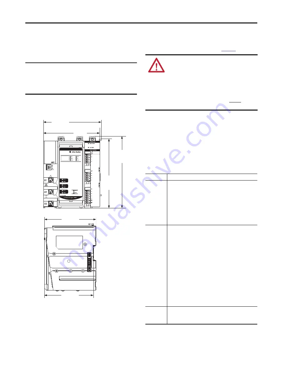
Dimensions
The controller dimensions are as follows.
Ground Considerations
You must ground DIN rails according to the Industrial Automation
Wiring and Grounding Guidelines, publication
1770-4.1
You can use the following DIN rails:
• EN50022 - 35 x 7.5 mm (1.38 x 0.30 in.)
• EN50022 - 35 x 15 mm (1.38 x 0.60 in.)
System Power Considerations
The CompactLogix 5480 controller provides power to a
CompactLogix 5480 system via RTBs that are connected to external
power supplies and installed on the controller.
The RTBs provide the following power to the system.
IMPORTANT
If any of the following conditions exist, the enclosure
must
be larger
:
• Any sides of the enclosure cannot transfer heat.
• More equipment is included in the system.
• Ambient temperature is higher than 20 °C (68 °F)
130.21 mm
(5.13 in.)
166.20 mm
(6.54 in.)
126.54 mm
(4.98 in.)
120.02 mm
(4.73 in.)
133.66 mm
(5.26 in.)
160.00 mm
(6.30 in.)
ATTENTION:
This product is grounded through the DIN rail to
chassis ground. Use zinc plated chromate-passivated steel DIN rail
to assure proper grounding. The use of other DIN rail materials (for
example, aluminum or plastic) that can corrode, oxidize, or are poor
conductors, can result in improper or intermittent grounding.
Secure DIN rail to mounting surface approximately every 200 mm
(7.8 in.) and use end-anchors appropriately. Be sure to ground the
DIN rail properly. See Industrial Automation Wiring and Grounding
Guidelines, Rockwell Automation publication 1770-4.1 for more
information.
Power Type
Description
MOD Power
System-side power that is used to operate the CompactLogix 5480 system.
MOD power is provided through the MOD power RTB and passed across the
MOD power bus.
• The total continuous current draw across the MOD power bus must not be
more than
10 A, max, at 18...32V DC
.
You must calculate the total MOD power that the controller and all local
Compact 5000 I/O modules draw to make sure that no more than 10 A of
MOD power is drawn.
(1)
• Confirm that the external MOD power supply is adequately sized for the
total MOD power bus current draw in the system, including the MOD
power inrush current requirements.
(1)
If you connect external power to both sets of MOD power RTB terminals, however, the local Compact 5000
I/O modules can draw a maximum of 10 A in addition to the current the controller draws.
SA Power
Field-side power that is used to power field-side devices. SA power is
provided through the SA power RTB and passed across the SA power bus.
• SA power is only required if your application includes local Compact 5000
I/O modules that are connected to devices that use SA power.
• If you are using
DC voltage
for SA power, the total continuous current
draw across the MOD power bus must not be more than
10 A, max at
18…32V DC
.
• If you are using
AC voltage
for SA power, the total continuous current
draw across the MOD power bus must not be more than
10 A, max at
18…240V AC
.
• You can use a 5069-FPD field potential distributor to establish additional
SA power buses in a CompactLogix 5480 system.
If your system includes AC and DC modules that require SA power, you
must use a 5069-FPD field potential distributor to establish a new SA
power bus.
You separate the module types by SA power bus. For example, install DC
module on the first SA power bus in the system and install the AC
modules on the second SA power bus in the system.
• Confirm that the external SA power supply is sized adequately for the
total SA power current draw in the system.
UPS Control
Control signals from an external UPS that let the controller save the state of
the program if power is lost. The external UPS provides the power that is
required to save the program via the MOD power RTB. A UPS is not required
for controller operation


