Component Interfacing, Module
Preparation, and Installation
Chapter 2
25
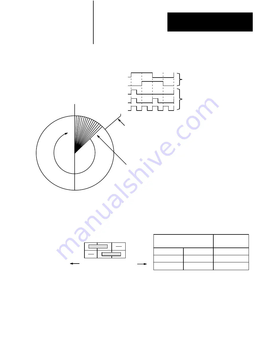
Figure 2.2
Example Encoder Diagram (250 Line)
Marker Pulse
at 360 o
Channel A
Channel B
X1
X2
X4
Quadrature
Multiplier
Single Encoder Line
250 Lines for
one rotation (360 )
o
Encoder
Output
Counts
Decoded
on the
Module
10403
Figure 2.3
Burg Pin Jumper Selection
Jumper
Labels
JPR1
JPR2
Jumper Setting
for x1 Multiplier
Left 1
2
3
Right
JPR1
1 + 2 (left)
2 + 3 (right)
1 + 2 (left)
JPR2
2 + 3 (right)
1 + 2 (left)
1 + 2 (left)
Jumper
Positions
Encoder Count
Multiplier
x 1
x 2
x 4
10402


