


Chapter 4
Geometries with orientation support
142
Rockwell Automation Publication MOTION-UM002F-EN-P - February 2018
Tip:
To use these Kinematic sample projects, on the
Help
menu, click
Vendor Sample Projects
and then click the
Motion
category.
The Rockwell Automation sample project's default location is:
c:\Users\Public\Public Documents\Studio 5000\Sample\ENU\v<current_release>\Rockwell Automation
See also
Define coordinate system frames
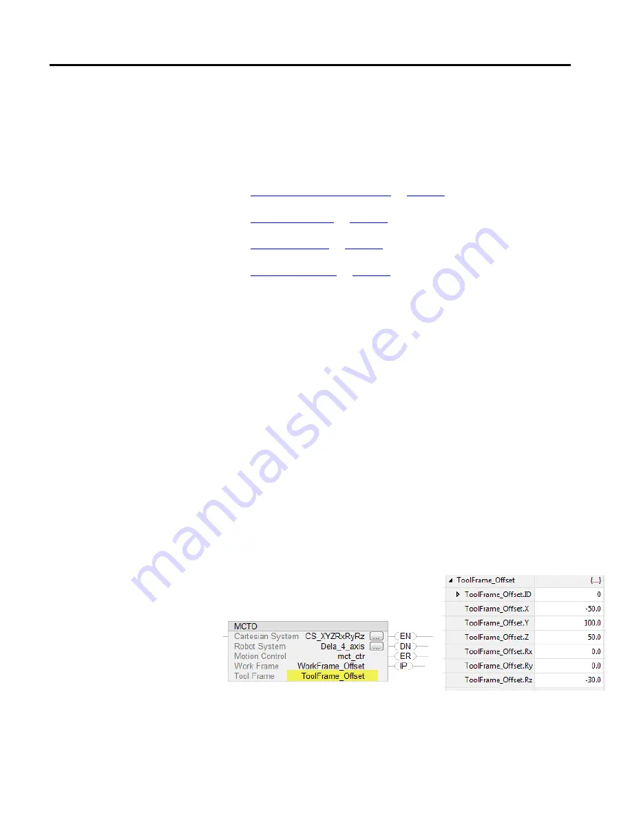
The tool frame offset is a set of (XYZRxRyRz) coordinate values that defines the
tool frame at tool center point (TCP) from the End of Arm (EOA) frame. The
X,Y,Z represents the translation coordinates that define the TCP from the EOA
frame and Rx, Ry, and Rz represents rotations around those axes.
Configure Offset parameters
Configure the tool frame offsets in the MCTO or MCTPO instructions in Logix
Designer application. Measure the offset distance and rotation for the tool frame
with respect to the robot’s EOA frame axes. Enter the degree of rotation offsets
into the Rx, Ry, and Rz tag members in units of degrees. Then enter the offset
distances into the X, Y, and Z tag members in coordination units.
Default values of the tool frame offsets are set as (0, 0, 0) for translation and (0, 0,
0) for rotation. This sets the EOA frame of the robot as a default TCP point. The
Tool Frame ID helps define multiple tools using the same tag variable with
different ID numbers. Set the ID member to a value greater than or equal to zero.
This image shows the Tool Frame offset configuration in the MCTO instruction
and offset values defined for a tool frame tag
ToolFrame_Offset
.
Status Attributes
ActiveToolFrameID and ActiveToolFrameOffset
Tool frame offsets