


This start-up procedure covers only the most commonly adjusted values using the 1336
PLUS
II
“Startup” mode. Refer to the
User Manual for detailed information.
The following procedure is written for users who have a Human Interface Module (HIM) installed. For users without a HIM,
respective external commands and signals must be supplied. It is also assumed that all parameters are at factory default set-
tings. Pay particular attention to steps marked with a “
✔
”.
ATTENTION:
Power must be applied to the drive to perform the following. Some of the voltages present are at
incoming line potential. To avoid electric shock hazard or damage to equipment, only qualified drive service
personnel should perform the following procedure. Thoroughly read and understand the procedure before beginning.
If an event does not occur while performing this procedure, Do Not Proceed. Remove Power by opening the branch
circuit disconnect device and correct the malfunction before continuing.
ATTENTION:
To avoid a hazard of electric shock when wiring or servicing the drive, verify that the voltage on the bus
capacitors has discharged. Measure the DC bus voltage at the + & – terminals of TB1. The voltage must be zero.
ATTENTION:
To guard against possible machine damage and/or personal injury caused by unintended motor rotation,
Do Not press the Start key (HIM) or issue a Start command (TB3) during this Start-Up procedure until instructed to do
so. Pressing the Start key or issuing a Start command will cause the drive to start.
❑
1.
Verify that AC line power and control power match the drive rating.
✔
❑
2.
Disconnect the load from the motor.
✔
❑
3.
If a Control Interface option is installed, verify that the Stop and Enable interlock
inputs are present. If this option is not installed, verify that jumpers are installed at
pins 3 & 4 and 17 & 18 of J2. In addition, [Input Mode] must be set to “Status.”
See page 2 for jumper locations.
❑
4.
If standard I/O is being used, verify that jumpers J8, J11 & J13 are properly set.
Refer to figure at right.
!
!
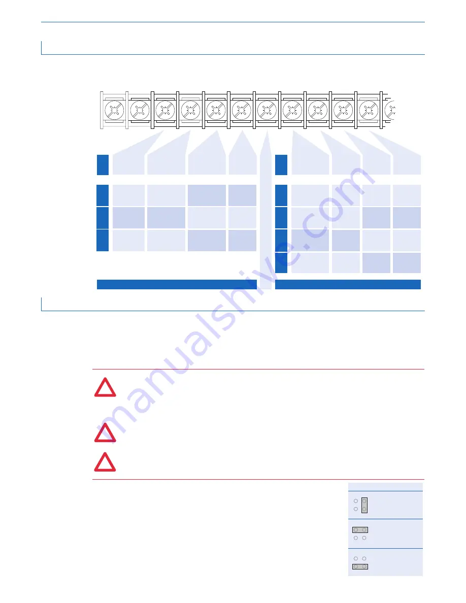
Analog I/O – TB2
Start-Up
1
TE
TE
Signal
Common
Only Present
on B Frame
& Up Drives
2
3
4
5
6
9
8
7
Isolated
Input 0 (–)
10V or 20mA
Isolated
Input 0 (–)
±
10V,
±
20mA
Isolated
Input 0 (–)
±
10V,
±
20mA
Isolated
Input 0 (+)
10V or 20mA
Isolated
Input 0 (+)
±
10V,
±
20mA
Isolated
Input 0 (+)
±
10V,
±
20mA
LA2
LA6
LA7
Analog I/O Option Slot A
Analog I/O Option Slot B
Isolated
Input 1 (+)
10V or 20mA
Thermistor
Isolated
Input (+)
Isolated
Input 1 (+)
10V or 20mA
Isolated
Input 1 (–)
10V or 20mA
Thermistor
Isolated
Input (–)
Isolated
Input 1 (–)
10V or 20mA
Pot.
Reference
+5V
1, 3
Single-Ended
Input 0
Pot., 10V or 20mA
Single-Ended
Input 1
Pot., 10V or 20mA
Signal
Common
S
i
g
n
a
l
C
o
m
m
o
n
Std.
LA1
LA3
LA4
LA5
Std.
or (select 1)
or (select 1)
Single-Ended
Input 2
2
Pot., 10V or 20mA
Isolated
Output 0 (+)
10V or 20mA
Isolated
Input 2 (+)
10V or 20mA
Single-Ended
Output 0
10V or 20mA
Single-Ended
Output 0
10V or 20mA
Isolated
Output 0 (–)
10V or 20mA
Isolated
Input 2 (–)
10V or 20mA
Non-Isolated
250 kHz
Pulse Output
Single-Ended
Output 1
20mA Only
Isolated
Output 1 (+)
10V or 20mA
Isolated
Output 1 (+)
10V or 20mA
Isolated
250 kHz
Pulse In (+)
0-20mA
Output
Return
Isolated
Output 1 (–)
10V or 20mA
Isolated
Output 1 (–)
10V or 20mA
Isolated
250 kHz
Pulse In (–)
Signal
Common
Single Ended
Output 1
0-10V Only
Single Ended
Output 0
0-10V Only
Single-Ended
Input 2
Pot., 10V or 20mA
1
If an Option Board is installed in Slot A, the +5V pot. reference will not be
available. If a 5V source is required, it must be user supplied.
2
Standard Analog Input 2 is maintained at this terminal – configure with J11.
3
10k Ohm potentiometer required.
Input Configuration (J8, J11, J13)
0-10V
J13 (TB2-3, Input 1)
(Pot Configuration Shown)
0-20 mA
Po
t
P
ot
Po
t
0-10V
J8 (TB2-2, Input 0)
(0-10V Configuration Shown)
0-20 mA
0-10V
J11 (TB2-6, Input 2)
(0-20 mA Configuration Shown)
0-20 mA
!
efesotomasyon.com - Allen Bradley,Rockwell,plc,servo,drive