background image

 DX32 Getting Started Guide 

AP10242 Issue 3 


3.


Front Panel 


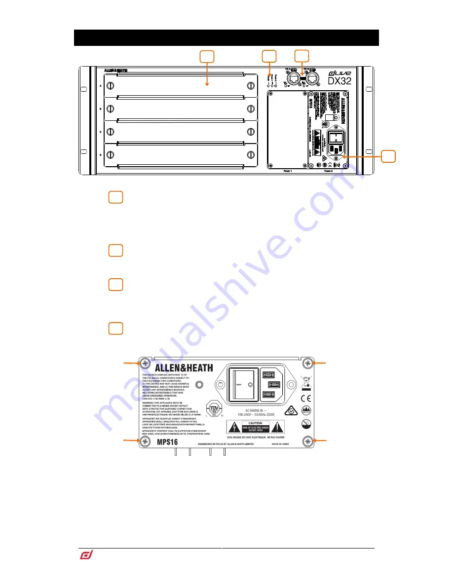
I/O modules

 – 4x slots for fitting 8ch analogue or digital I/O modules. To fit 

a module, switch the expander off, remove the blank panel by loosening the 2 thumb 

screws, slide the module into the slot and press it firmly into the mating connector, 

then secure it by tightening the thumb screws. 

Use the dLive 

I/O 

screen to patch signals from or to the DX expander.


Status indicators

 – Power ON indicators for the 2 power supplies. The 

Ready indicator lights up when the output sockets are ready to pass audio after power 

up. 


DX links

 – Dual redundant EtherCon ports for connection to a dLive MixRack 

or  Surface  over  Fast  Ethernet  (IEEE  802.3  Layer  2  compliant).  A  single  Cat5e  (or 

higher) cable carries 32x32 channels of 96kHz audio and control. Use two cables for 

redundancy. 


Power Supply

 – Hot swappable power supply with mains IEC socket and 

On/Off rocker switch. To remove or replace, loosen the 4 screws indicated below and 

slide the PSU out of the slot. 


 DX Expanders ship with one PSU fitted. A second PSU can be fitted for redundancy 

(part number MPS-16). Remove the 4 screws securing the blank panel using a star 

Torx T8 screwdriver, slide the PSU into the slot, and tighten the 4 screws indicated 

above.  The  Expander  will  automatically  switch  between  the  supplies  without 

interruption to the audio should one fail. 

 Heed the safety warnings printed on the panel.  

A plastic P-clip cable clamp is provided to secure the mains cable. Slot the cable in 

or lock it in place using a star Torx T20 screwdriver to refit the clamp around the cable. 


Summary of Contents for dLive DX32

Page 1: ...DX Expander Getting Started Guide DX32 Before starting please check www allen heath com for the latest dLive firmware and documentation AP10242 ...

Page 2: ...n Heath website www allen heath com legal Repair or replacement under the terms of the warranty does not provide right to extension or renewal of the warranty period Repair or direct replacement of the product under the terms of this warranty may be fulfilled with functionally equivalent service exchange units This warranty is not transferable This warranty will be the purchaser s sole and exclusi...

Page 3: ...t For more information on dLive setup and mixing functions please refer to the dLive Firmware Reference Guide available for download at www allen heath com Check for the latest version of this Getting Started Guide You can also join our Allen Heath Digital Community to share knowledge and information with other dLive users General precautions Protect the equipment from damage through liquid or dus...

Page 4: ...d 4x M6 screws and washers for rack mounting Contents IMPORTANT Read before starting 3 1 Introduction 5 2 Installing the Expander 6 2 1 Free standing 6 2 2 Rack mounting and flight casing 6 2 3 Rack ears 6 3 Front Panel 7 4 Rear Panel 8 5 I O Modules 9 6 Connect and power up 10 6 1 MixRack connection 10 6 2 Surface connection 10 7 Dimensions 11 8 Technical specs 12 ...

Page 5: ...the Allen Heath website to find out more about dLive The MixRack is the heart of any dLive system It houses the XCVI processing core complete with audio I O control and audio networking ports The Surface is effectively a network controller for the MixRack with the addition of built in audio I O and audio networking ports The DX Expander adds remote modular I O to a dLive system It provides 4x 8ch ...

Page 6: ...e use we recommend that you use a professional grade flight case Use the M6 screws and washers supplied with the product to rack mount Ensure natural convection of airflow around the unit by allowing good ventilation below in front of and behind the unit Rack equipment known to produce a significant amount of heat should not be mounted directly below the unit Forced convection by means of a rack m...

Page 7: ...2 compliant A single Cat5e or higher cable carries 32x32 channels of 96kHz audio and control Use two cables for redundancy Power Supply Hot swappable power supply with mains IEC socket and On Off rocker switch To remove or replace loosen the 4 screws indicated below and slide the PSU out of the slot DX Expanders ship with one PSU fitted A second PSU can be fitted for redundancy part number MPS 16 ...

Page 8: ...c feet Removable plastic feet Use a flat head screwdriver to remove or reposition the plastic feet Kensington Lock A slot for fitting standard Kensington anti theft security devices Fan Ultra quiet fan Make sure the ventilation opening is not obstructed 1 2 3 3 1 2 ...

Page 9: ...ternally or externally sourced M AOUT Line level balanced XLR outputs Nominal level 4dBu The outputs are relay protected to prevent power on or off thumps M DIN 4x stereo AES3 inputs with SRC 32kHz 192kHz sampling rate Sample Rate Conversion can be bypassed for each socket for 96kHz operation only M DOUT 4x stereo AES3 outputs 44 1kHz 48kHz 88 2kHz or 96kHz switchable with LED indication of sample...

Page 10: ... firmware during power up This can take up to 20 seconds During this time the Lnk Err indicators on the DX Expander flash at a fast rate Once updated normal flash rate is restored 6 2 Surface connection Plug a touring grade CAT5e or higher specification cable up to 100m long between the DX Expander and Surface DX ports Use two cables for redundancy if required Refer to www allen heath com for cabl...

Page 11: ...DX32 Getting Started Guide 11 AP10242 Issue 3 7 Dimensions 481 60 433 00 311 00 289 00 24 30 465 10 101 60 177 00 ...

Page 12: ... at 24V Digital Inputs AES3 2 Ch XLR 2 5Vpp balanced terminated 110 Ω SRC on each pair range 32k 192kHz with bypass option Outputs Temperature Analogue XLR Outputs Balanced Relay protected Operating Temperature Range Output Impedance 75Ω Fitted with MPS16 V1 300w 0 C to 35 C 32 F to 95 F Nominal Output 4dBu 0dB meter reading Fitted with MPS16 V2 250w 0 C to 40 C 32 F to 104 F Maximum Output Level ...

Reviews: