

All Motion
www.allmotion.com
30097 Ahern Avenue, Union City, CA 94587 Telephone 408.460.1345 Email
012513
Make sure address switch is detented exactly on position number 1.
(After resetting, power must be cycled to establish new address.)
Re-check that correct com port is selected.
Confirm good ground between PC and negative terminal of power
supply. First, measure resistance with power off; then check for voltage
drop with power on. Repair poor ground connections.
Issue command /1& and verify that a response identifying the product and
firmware version is received. If ok, motor connection may be miswired or
loose. If not ok, re-install USB driver. Continue to next item if not resolved.
Check continuity of communication data to EZStepper board at point 1
in diagram below. If not present, check at other points indicated.
Suspect failed component or faulty wiring/connector between point
where signal is absent and last point where signal is present.
If motor does not
respond to commands:
If motor misses steps at high speed:
Increase either the Move current or the supply voltage.
To increase Move current, issue an "m" for Fast Move Current and/or "l"
command (lower case L) for Slow Move Current. Example: /1m75 = set
current to 75% max.
Step misses typically happen in the middle of a move, where the motor
"catches" in the beginning and end, but stalls in the middle.
If motor direction is not consistent:
Check that coils of motor are securely connected at both ends.
This is typically caused when one of the coils has a loose connection.
EZ Stepper
+
B
A
NOTE: If using RS232 Converter, disregard instructions for USB.
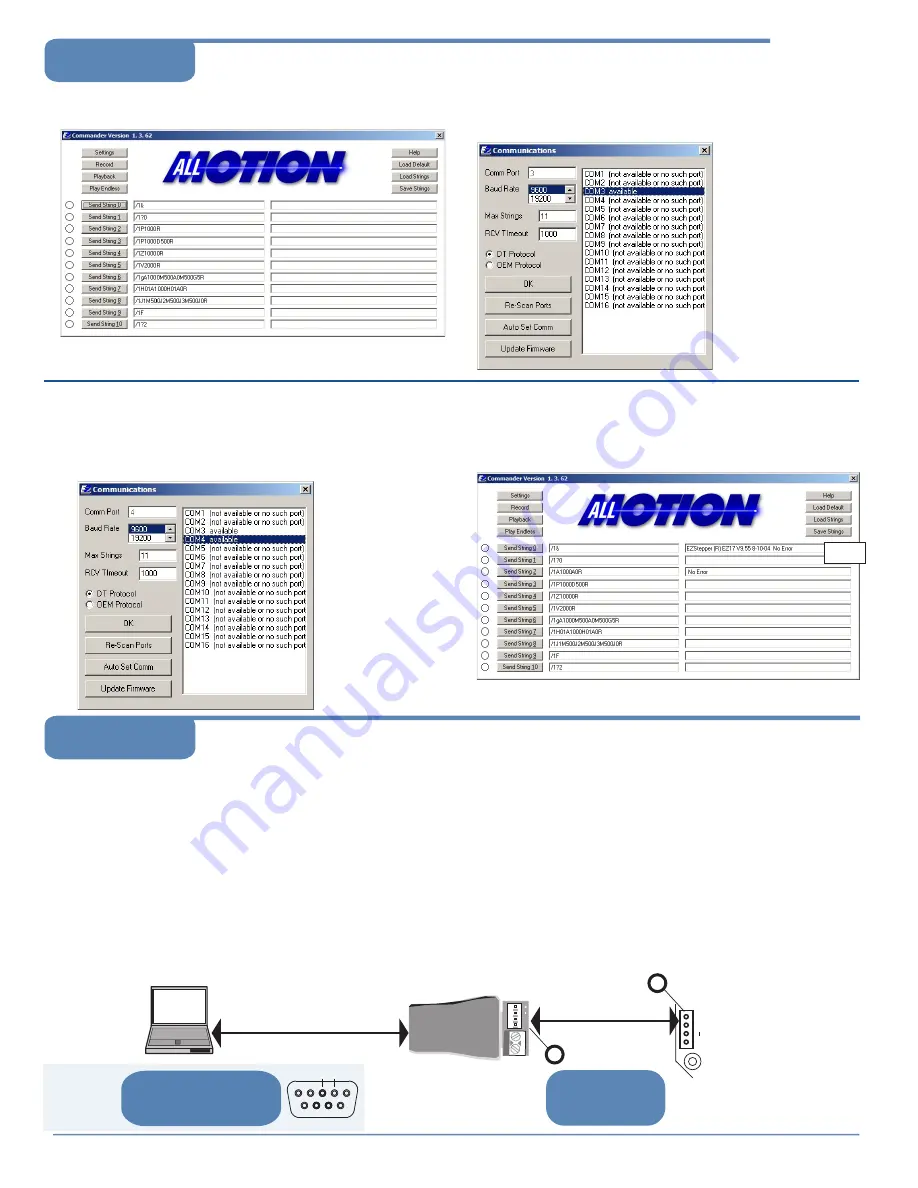
2
Click the
Settings
button to open the Communications window.
• Click Re-Scan Ports; note available ports; then click OK to close.
1
Open EZCommander.
3
Plug USB cable into the PC.
• Click Settings button, then Re-scan Ports. A new comm port
will become available (will be com1 if using RS232 Converter).
•
Select the newly available comm port and click OK to close the
Communications Window.
Command strings
↑
Return messages
↑
4
Issue commands :
• Enter string in a left-hand field.
• Press adjacent
Send String
button to issue command.
• See return message in field to right.
Start with communications
cable unplugged.
Example
message
NOTE:
USB cable
is disconnected for
this step.
NOTE: If using RS232 Converter, disregard instructions
for USB.
EZ Bus cable
Pins A & B
1
2
Pins A & B
At both sets of A & B pins,
confirm 3V P-P pulses
centered on +2.5V. See
points 1 and 2.
NOTE: Signal presence at point 1
suggests problem in motor, EZStepper
board, or wiring to motor.
USB-to-RS485 Converter
shown.
2
3
If using
RS232-to-485
Converter
At DB9 connectors pins 3 and 2,
see 12V P-P pulses 100
µ
sec wide
(@9600 baud). Check at cable end
and at Converter connector.
A
B
Troubleshooting
EZ17,23/Page 2
Using EZCommander
TM


