background image


25


Figure 51 

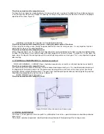
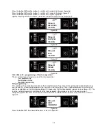
By pressing the button SET and the button 1 we activate (ON) or deactivate (OFF) the program 1 for the corresponding 
day in the week starting from Monday, up to Sunday as shown in figures 52 and 53. The transition from day to day is 
performed by pressing the button SET. 


Figure 52 


Figure 53 

By pressing the button SET, a transition is made towards setting of another program and its activation for every day in 
the week separately (in the same manner as it was done for program 1). Repeat the same procedure for the remaining 
two programs (program 3 and 4). The indicator that the programming is active will be shown in the display. 

Attention: Deactivate the daily program if you want to use weekly  rogramming. 

 
Weekend programming 

The weekend programming enables programming, switching on and switching off of the stove (twice a day) during the 
weekends (Saturday and Sunday). Activate the weekend programming only if the daily and weekly programming has 
been deactivated. 
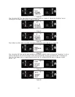
The first four steps during programming are the same as in the daily programming (figures 39-42). Press button 4 and 
then press button 5 three times and the display will look the same as shown in figure 54. 


Figure 54 

By pressing the button SET, we activate the weekend program as shown in figure 55. 


Figure 55 

12:00 
N-2-3- 02 
STOP 
PROG-1 

ON 
N-2-3- 10 
SUNDAY 
PROG-1 

ON 
N-2-3- 01 
MONDAY 
PROG-1 


N-2-4 
PROGRAM  
WEEK-END 

ON 
N-2-4- 01 
CHRONO 
WEEK-END 

Summary of Contents for COMMO

Page 1: ...1 PELLET STOVE COMMO INSTALLATION OPERATION AND MAINTENANCE MANUAL Pellet woody biomass biofuel ...

Page 2: ...surroundings and transforming it into oxygen for air and carbon of the plant during its whole life The use of non renewable fossil fuels coal oil gas contrary to what happens with wood releases into the atmosphere enormous quantities of carbon dioxide CO 2 accumulated for millions of years thus causing the greenhouse effect The use of wood as fuel is therefore perfectly balanced with the environme...

Page 3: ... Accidents occurred due to any modifications and repairs not approved by ALFA PLAM Poor maintenance Unpredictable events Accidents occurred due to the use of spare parts that are not original spare parts or that are not intended for these models of the stove The installer of the stove shall take the full responsibility for the installation 2 1 THE BASIC CHARACTERISTICS OF THE USER The user must ha...

Page 4: ...the electrical system grounding Always use the personal protective equipment and all the protective means prescribed by applicable local regulations Always ensure sufficient servicing space required for any maintenance and repairs of the stove 3 1 PLACING THE STOVE We advise you to unpack the stove only when it is put in the place where it is to be installed The stove stands on plastic legs with c...

Page 5: ...chimneys can be used or chimneys may be made of pipes that must be thoroughly insulated double wall and sealed in order to prevent condensation in them The discharge pipe must not be connected with other systems of any type such as the systems for discharging smoke from the combustion chamber exhaust grid or air distribution systems etc Furthermore the flue pipe must not be located in closed or se...

Page 6: ...t places where the elevation above the sea level is higher than 1 200 meters 100 recommendable Table 1 When you use a connecting pipe between the stove and the discharge flue pipe you must also use a T coupling as it is shown in Figures 5 and 6 with the cover for the purpose of cleaning plug next to the stove The application of this T coupling must enable the collection of ashes generated inside t...

Page 7: ... flue pipe should pass through This varies depending on the type of installation diameter of the flue pipe see Table 1 and the type of the wall or roof the flue pipe should pass through See Table 2 The insulation must be made of mineral wool with nominal density higher than 80 kg m 2 Figure 4 Figure 5 1 Armature 80 100 2 T shaped pipe fittings Figure 6 5 4 3 6 1 2 7 Ø100 Ø80 7 Ø100 Ø80 ...

Page 8: ... wind resistant top of the chimney distances and stove placing the distances shown in Table 3 must be met Roof inclination Distance between the roof ridge cover and the chimney Minimum height of the chimney measured at the upper opening at the chimney outlet α Distance in meters Height in meters 15 0 Less than1 85 m More than 1 85 m 0 50 above the roof ridge cover 1 00 meter from roof pitch 30 0 L...

Page 9: ...es should be connected to the electric power supply Our stoves have electric cables suitable for medium temperatures If the cable should be replaced e g because it is damaged please consult our authorized technical personnel our experts Before you connect the stove to the electric power supply ensure that The characteristics of the electric system correspond to the data i e specification stated on...

Page 10: ...handles are cool before you touch them NEVER START UP THE STOVE even if only one of the security devices is faulty improperly set or does not function Do not make any modifications for whatever reason except those allowed and explained by the manufacturer Always use original spare parts Never allow the components to completely wear out before you replace them Replacing a worn out part i e componen...

Page 11: ...ing agent Ensure that the stove is fixed well in order to prevent any movement Ensure that the box for ashes is inserted and that it is completely closed so that the door is properly leaned against the inner box Ensure that the stove door is tightly closed while the stove is in operation Remove ashes with a vacuum cleaner only when the stove is completely cool Never clean the stove surfaces with a...

Page 12: ...d in the openings of the crank the pins where the springs for cleanings are connected and shake them after lifting them and lowering them for few times as shown in figure 12 Figure 12 Figure 13 LOWER SMOKE CHAMBER It should be cleaned manually at each consumed 90 100 kg of pellets two full tanks Raise the cover of the pellet tank In the tank in the front upper part under the cover there is a butto...

Page 13: ...ape of the sealing tape with the use of high temperature resistant glue This is very important for good door sealing 6 2 CLEANING and MAINTENANCE for maintenance workers THE FLUE CHANNELS CHIMNEY these should be cleaned every six months or after burning two tons of pellets The stove and ash must be completely cool This wind resistant flue channel chimney must be checked and cleaned each year This ...

Page 14: ...ay have various intensities The stove manufacturer shall not be liable for the use of fuel pellets of inadequate quality or for the poor operation of the stove due to such fuel 8 1 FUEL PELLET STORAGE Pellets must be stored in a dry place which is not too cold In fact cold and wet pellets with a temperature of around 5 0 C decrease the thermal power of the fuel and require additional stove cleanin...

Page 15: ...ay special attention to pipes gradients which should be 0 5 5 mm per meter and to ventilation of the system boiler pipes radiators Put thermo manometer on pressure line that will show water pressure in the system and water temperature on the boiler outlet 1 The COMMO Stove 2 Chimney connector 3 Distribution pipe 4 Expansion container in the stove 5 Safety valve in the stove 6 Radiator valve 7 Radi...

Page 16: ...n expansion tank with 10l volume Function of the tank is pressure stabilisation in the boiler and in the heating system installation Factory setting of the pressure in the tank is 1 bar 11 5 FILL AND DRAIN COCK Purpose of the cock is filling and draining of the installation It is positioned on the rear bottom side Inlet connector is R1 2 and outlet connector has hose extension 12 FILLING THE INSTA...

Page 17: ...h button display Display shows information about furnace operation status Accessing the menu user can get various kinds of information review and can make available adjustments according to level of access Figure 17 shows an example of a display representation Buttons 1 increase of the temperature and the program functions for changing the date and time 2 reduction of the temperature and the progr...

Page 18: ...menu item set modulations are memorised 6 Increasing power MENU Move son to the previous menu item SETTINGS Moves on to the previous submenu set modulations are memorised Table 5 15 2 OPERATION MODE USER 15 2 1 Stove ignition When the stove is connected to power supply you should turn the switch which is at the back side of the stove to position 1 Then the following is shown in the display Figure ...

Page 19: ...t is sufficient to press the buttons 1 or 2 The display will show the current state of the set temperature TSET The stove has been factory set with a temperature of water in the boiler of 65ºC and at room temperature of 20ºC By pressing the button 1 the message SET TEMP WATER is shown figure 26 i e adjusted value of the water temperature in the boiler Thus with button 1 we increase and with button...

Page 20: ...ssing the buttons 5 and 6 the message SET OUTPUT appears which means setting the output power With button 6 we increase and with button 5 we reduce the power of the stove Level 1 is minimal and level 5 is maximal power Figure 29 15 2 7 Cleaning of the boiler During normal functioning in the operational mode in intervals which have been set to 30 minutes the mode BOILER CLEANING switches on whose d...

Page 21: ...sed for access to the next level of the submenu and in the end the button 3 is used for setting a value and transition to the next menu item The button 6 is used for transition to the previous submenu and the adjusted settings are memorized The button 5 is used for transition to the next submenu and the adjusted settings are memorized The button 4 is used for transition to higher menu level and th...

Page 22: ... enables setting of the daily functions of the chronothermostat The stove can be ignited and switched off twice as desired and this is regulated by programming having in mind that sufficient time is required between the switching off and the new ignition so that the stove could cool It is necessary that the time and date are precisely set menu 01 The functions of switching on and switching off of ...

Page 23: ...he button SET twice and the representation on the display will be the same as in figure 44 The buttons 1 or 2 are used for adjusting the time of the first ignition of the stove during the day By pressing the button SET the display will have the same appearance as in figure 45 and the time of the first switching off of the stove is set by pressing the buttons 1 or 2 Figure 44 Figure 45 N 2 1 ENABLE...

Page 24: ...d switching off Attention carefully perform the programming generally avoiding overlapping of the time activation and or deactivation on the same day in different programs The programming procedure is the following The first four steps during programming are the same as in the setting of the daily program figure 39 42 Press the button 4 and then press the button 5 twice and the display will have t...

Page 25: ...tive will be shown in the display Attention Deactivate the daily program if you want to use weekly rogramming Weekend programming The weekend programming enables programming switching on and switching off of the stove twice a day during the weekends Saturday and Sunday Activate the weekend programming only if the daily and weekly programming has been deactivated The first four steps during program...

Page 26: ... if you wish to engage weekly program Weekend program always keep inactive if using weekly program in levels 1 2 3 and 4 Activate weekend program only after deactivating the weekly program 15 4 4 Menu 03 language selection Provides selection between available languages Level 1 Level 2 Value Menu 03 choose language Menu 03 01 Italian Set Menu 03 02 French Set Menu 03 03 English Set Menu 03 04 Germa...

Page 27: ...lable to the User 15 5 ALARMS In case of malfunction controller turns on and warns for irregularities with different kinds of alarms Following alarms are envisaged Source of alarm Display message Smoke temperature probe ALARM SOND FUMI Smoke temperature exceeding ALARM HOT FUMI Ignition failure MANCA ACCENSIONE Fire extinguishing during work mode MANCANO PELLET Power outage BLACK OUT Screw feeder ...

Page 28: ...erature or screw feeder temperature is too high and then message FAIL SIC appears This is additional safety device To return to normal working mode you should wait for furnace to shuts down smoke fan works Cooling lasts for twenty minutes After that renew safety thermostat function that blocked the furnace take plastic cap off and press thermostat button until silent metal noise sounds It is locat...

Page 29: ...c Work Boiler cleaning 30 sec Boiler cleaning Off 30 sec Off Table 7 In all cases when duration of power outage was longer than 30 seconds furnace shuts down When AC power is on again the power outage was longer than 30 seconds then the following is shown in the display figure 69 Figure 69 Figure 70 In order to cancel the alarm it is necessarily to hold the button 4 pressed for about 2 seconds and...

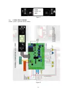
Page 30: ...30 Figure 71 5 6 CONNECTION SCHEME Bellow is given a typical connection scheme Figure 72 07 47 18 5ºC 35 OFF ...

Page 31: ... combustion chamber 1 Wood pellet reservoir is empty 2 Transport spiral is blocked 3 Helical geared motor is broken 4 Electric card is broken 1 Fill the reservoir 2 Empty the reservoir and unblock the spiral screw feeder 3 Replace helical geared motor 4 Replace electric card Fire is not burning or furnace automatically shuts down 1 Wood pellet reservoir is empty 2 Combustion chamber is not filled ...

Page 32: ...h materials things and if necessary report the disposal of such things CAUTION The disassembly of the stove may only be performed when the chamber of the stove is not in operation and when the stove is unplugged there is no electric power supply Remove all the electric parts Discard the batteries of the electronic card and remote controller into adequate containers in accordance with the standards...

Page 33: ... Handling 2 3 The Responsibility of the Installer 3 0 The Installation Incorporation of the Stove 3 1 Placing the Stove 3 2 The Smoke Discharge System 3 3 The Insulation and Diameter of the Openings Holes on the Roof or on the Wall 3 4 The Intake of Combustion Air 3 5 The Connection to the Electric Power Supply 4 0 Important Instructions 5 0 Warning of the Safety Measures for the Maintenance Worke...

Reviews: