background image

ALFA WiFi USB Adapter User Guide


19


Step 4  Click 

Start PIN 

on the following screen. 

Figure 2-22 Start PIN 

Step 5  When Figure 2-16 appears, the configuration is complete. 

Note:


The default PIN code of the AP always can be found in its label or User Guide. 

2.1.3  Link Information


Click the 

Link Information 

icon  


of the Utility and you will see the following screen displaying 

the receiving and transmitting statistical information. 

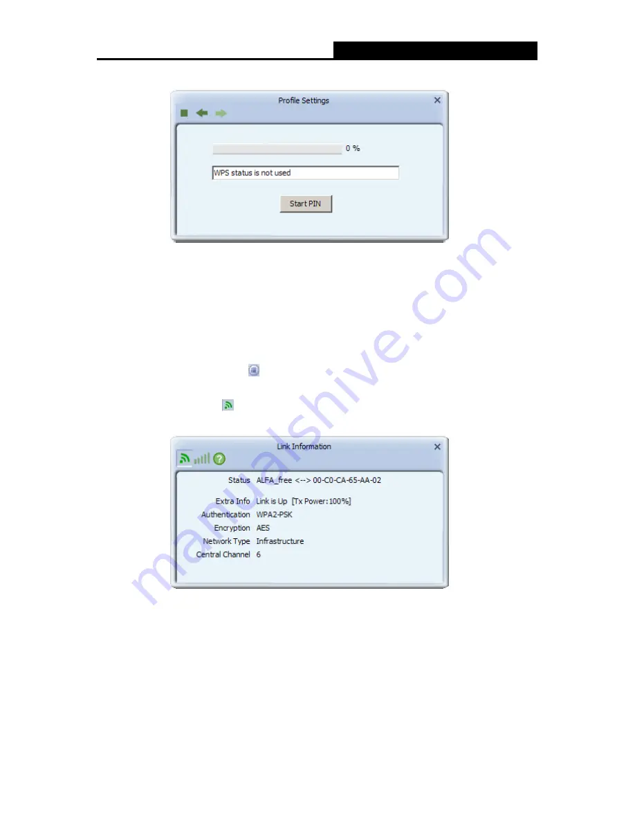
Click the 

Link Status 

icon 

, you can view the current linking status of the Adapter as shown in 

the figure below. 

Figure 2-23 Link Status 

The following table describes the items found on the Link Status screen. 


Status - 

Current connection status.  If no connection, it will show Disconnected. Otherwise, 

the SSID and BSSID will show here. 

Extra Info - 

Here displays the link status in use. 

Authentication - 

Shows the authentication mode in use. 

Encrtption - 

The encryption type in use is displayed here. 

Summary of Contents for ALFA WiFi USB

Page 1: ...Wireless USB Adapter User Guide...

Page 2: ...rference by one or more of the following measures Reorient or relocate the receiving antenna Increase the separation between the equipment and receiver Connect the equipment into an outlet on a circui...

Page 3: ...s transmitter must not be co located or operating in conjunction with any other antenna or transmitter This equipment has been SAR evaluated for use in hand SAR measurements are based on 5mm spacing f...

Page 4: ...r software from your PC 6 Chapter 2 Configuration 8 2 1 Configuration of Utility 8 2 1 1 Site Survey 9 2 1 2 Profile 9 2 1 3 Link Information 20 2 1 4 Advanced 22 2 1 5 About 23 2 1 6 An example for a...

Page 5: ...you will be prompted Found New Hardware Wizard click the Cancel button and run the Setup Wizard program on the CD ROM Note The Setup steps for Windows XP Vista 7 Win 8 Win10 are very similar so the fo...

Page 6: ...ALFA WiFi USB Adapter User Guide 2 2 Then you ll see the screen as below You can choose which to be installed Figure 2 2 Setup Type...

Page 7: ...dapter Utility please select the Ralink Configuration Tool and click Next II If you only want to use the Microsoft Zero Configuration Tool to configure the wireless connection please select Microsoft...

Page 8: ...een for installing will appear Figure 2 5 Setup Status 7 After the files have been successfully copied the screen in Figure 2 6 will appear Click the Finish button to finish the installation and reboo...

Page 9: ...ully you should see an icon or in your system tray 1 2 Uninstall Software 1 2 1 Uninstall the utility software from your PC 1 On the Windows taskbar click the Start button point to Programs Ralink Wir...

Page 10: ...click the Start button and then click Control Panel 2 Double click the System icon click on the Hardware tab in the System window 3 Click on the Device Manager button double click Network adapters and...

Page 11: ...by clicking Start All programs Ralink Wireless Ralink Wireless Utility If the icon still does not appear the driver or utility may be installed incorrectly or the adapter is unplugged please try agai...

Page 12: ...h the list at any time Add to Profile Highlight an SSID and click the Add to Profile icon to add the network to the profile Connect Highlight an SSID and click the Connect icon to connect to an availa...

Page 13: ...of profile preset to PROF indicate 1 2 3 SSID The access point or Ad hoc name Authentication Indicates the authentication mode used Encryption Indicates the encryption type used 2 1 2 1 Add a profile...

Page 14: ...access point 2 An Ad Hoc network contains only clients such as laptops with wireless desktop adapters All the adapters must be in Ad Hoc mode to communicate 2 In the following screen select the corres...

Page 15: ...nnection Then click the Next icon to continue Figure 2 6 Enter the Key 4 The Pre logon Connect configuration page as shown in Figure 3 7 will then appear Click the Next icon to continue Figure 2 7 Use...

Page 16: ...ser Guide 12 Figure 2 8 Profile Added Successfully 2 1 2 2 Delete a profile Highlight the desired profile name on Profile List and click the Delete icon The profile will be removed from the list Figur...

Page 17: ...From the Profile List screen shown in Figure 3 3 click the Import icon Then the Import 2 Profile screen will appear Browse to the directory where the profile is located 3 Highlight the profile name 4...

Page 18: ...If the wireless card supports Wi Fi Protected Setup WPS you can establish a wireless connection between wireless card and router using either Push Button Configuration PBC method or PIN method For th...

Page 19: ...e Access Point by Push Button Configuration PBC method Step 1 Press the WPS button on your Access Point device Figure 2 12 Press the WPS Button Step 2 Click the Add to Profile icon on the screen as Fi...

Page 20: ...Method Figure 2 16 If your Access Point supports Wi Fi Protected Setup and the PIN method you can add the adapter to the network by the following two ways 1 Enter the PIN into my Access Point Step 1 C...

Page 21: ...e of the adapter here takes 33716435 in the screen for example into the configuration utility of the AP For the detailed instructions of the AP configuration please refer to the User Guide of the AP F...

Page 22: ...FA_free for example and then tick PIN numeric code on the screen below Figure 2 20 Step 3 Choose the Config Mode as Registrar and enter the PIN of AP here takes 90377211 for example into the field bes...

Page 23: ...reen displaying the receiving and transmitting statistical information Click the Link Status icon you can view the current linking status of the Adapter as shown in the figure below Figure 2 23 Link S...

Page 24: ...Throughput Link Quality Displays connection quality based on signal strength and TX RX packet error rate Signal Strength This shows the strength of the signal Link Speed Shows current transmit rate an...

Page 25: ...ceived Successfully The number of frames successfully received Received With CRC Error The number of frames received with a CRC error Dropped Due To Out of Resource The number of frames dropped due to...

Page 26: ...displaying the wireless card and driver version information Figure 2 28 About Version The version of the following items Utility Date The creation date of this utility Driver Date The creation date o...

Page 27: ...s default if you are not sure about them 4 Highlight the profile named Test on the profile list and click Active on the Profile screen The utility will establish a connection with this AP by configure...

Page 28: ...ve not installed SP2 for Windows XP the screen above will not be available 3 Enter the key and click Connect to continue Figure 2 31 Enter Network Key 4 If the connection is finished you will see the...

Page 29: ...s router based on the selected card connecting to the Internet which will make the APs of the LAN share the Internet Figure 3 2 The configuration utility screen will then appear as shown in the figure...

Page 30: ...AP for example you can name it My Network instead of the default name SoftAP 2A Step 2 Here you can select country region and set the AP s channel Figure 3 5 Channel Select the channel from the drop...

Page 31: ...ppear Here you can make some advanced settings and click Apply to make these settings take effect Figure 3 8 Beacon Interval ms Enter a value between 20 1000 milliseconds for Beacon Interval here The...

Page 32: ...hlight an existing Mac address in the list and click to remove it from the list as shown in Figure 3 11 When clicking you will clear all the Mac addresses in the Access Control List as Figure 3 12 Fig...

Page 33: ...ALFA WiFi USB Adapter User Guide 29 Figure 3 10 Add an Mac Address to the List Figure 3 11 Remove an existing Mac Address from the List...

Page 34: ...B Adapter User Guide 30 Figure 3 12 Clear All MAC Addresses 3 4 Associate List Figure 3 13 shows the link status page It displays detailed station information of current connection Figure 3 13 Mac Tab...

Page 35: ...n AID Raise value by current connection Power Saving Mode Support Power Saving Mode on the currently connected station Status The link status of the current connection 3 5 About The About page display...

Page 36: ...ssion statistical techniques embedded in the receiver can recover the original data without the need for retransmission To an unintended receiver DSSS appears as low power wideband noise and is reject...

Page 37: ...vices must be configured with the same SSID This is typically the configuration parameter for a wireless PC card It corresponds to the ESSID in the wireless Access Point and to the wireless network na...

Reviews: