background image

AHE00046EN 1904

2

Alfa Laval is a trademark registered and owned by Alfa Laval Corporate AB. 

Alfa Laval reserves the right to change specification without prior notification. 

Index

1. 

Important information

1.1  Disclaimer...................................................................................................................................3

1.2  Intended use...............................................................................................................................3

1.3 

Where to find product information

 ..............................................................................................3

2. 

Product description

2.1  General information and application...........................................................................................4

2.2 

Standard configuration

 ...............................................................................................................4

2.3  Options .......................................................................................................................................5

2.4  Code description ........................................................................................................................5

3. 

Product labels

...........................................................................................................................6

4. 

Unpacking and lifting

 ...............................................................................................................8

5. 

Installation

5.1  Mounting dimensions .................................................................................................................9

5.2  Mounting bracket ......................................................................................................................10

5.3  Technical spaces ......................................................................................................................10

5.4  Refrigerant connections ...........................................................................................................10

5.5  Drain line ..................................................................................................................................10

5.6  Electrical connections...............................................................................................................11

5.7  Electric defrost capacities.........................................................................................................16

6. 

Maintenance

6.1  Fan replacement ......................................................................................................................17

6.2  Driptray .....................................................................................................................................17

6.3  Side covers...............................................................................................................................18

6.4  Coil heater elements replacement............................................................................................18

6.5  Driptray heater elements replacement .....................................................................................18

7. 

Spare parts

..............................................................................................................................19

Summary of Contents for Optigo CD

Page 1: ...ORIGINAL INSTRUCTIONS AHE00046EN 1904 Alfa Laval Optigo CD Instruction manual Product description Product labels Unpacking lifting Installation Maintenance Spare parts...

Page 2: ...formation and application 4 2 2 Standard configuration 4 2 3 Options 5 2 4 Code description 5 3 Product labels 6 4 Unpacking and lifting 8 5 Installation 5 1 Mounting dimensions 9 5 2 Mounting bracket...

Page 3: ...tion until the conformity of the complete machine or cooling system has been declared according to the following standards and directives Pressure Equipment Directive 2014 68 EU Machine Directive 2006...

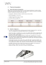
Page 4: ...ons and dedicated thicker tubes for CO2 application Optigo CD coolers are available with 1 to 4 fans Fan diameters 300 or 400 mm blowing through the coil All models are standard fitted with AC fan mot...

Page 5: ...asing and frame SSC Re heating coil RH Available for CD300 only Switch on off SW Fan motors wired to connection box CB 2 4 Code description CD E H E 40 2 2 B S 230V BOP PC E CB AL 7 0 CU IS 1 2 3 4 5...

Page 6: ...S R L Italy 04 2019 Model O A 1106756 CDXLE302 CS 230V BOP SSA CBM CA 4 0 CU Item ID 3289216404 Serial no AP 5002763 Sn Coil PED data ART 4 3 Max DN 9 mm Fluid Group 2 Coil Ts 125 60 C Ps 80 bar Pt 1...

Page 7: ...mber 7 Electrical warning Electrically powered component Switch off power supply before any maintenance or instal lation activity 8 Fan direction Sticker indicates fan rotation direction 9 Moving part...

Page 8: ...orks may be lowered and the remaining packaging materials can be removed cardboard CD300 crate for CD400 max 4 max 2 In order to avoid damage to the air cooler or fall ing of the unit ensure that the...

Page 9: ...e for download on www alfalaval com Dimensional drawings 5 Installation Always follow guidelines and instructions as given in the air cooler product manual AHE00042 W cooler model Dimensions mm Shippi...

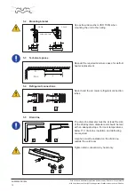
Page 10: ...e required minimum space for defrost heater replacement 25 10 20 12 CD300 CD400 washers ISO 7093 Never bend the air cooler refrigerant connection tubes The drain line diameter must be at least the siz...

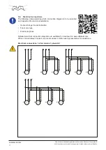
Page 11: ...r electrical installation Heat exchanger model indication Fan motor type Electrical options Detailed electrical connection diagrams are available for download on www alfalaval com When in doubt always...

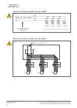
Page 12: ...M1 TK1 PE TK TK M 3 U V W U1 V1 W1 PE TK TK M1 TK1 PE TK1 TK2 M 3 TK3 U1 V1 W1 PE TK TK M2 TK2 M 3 U V W U1 V1 W1 PE TK TK M1 TK1 PE TK1 TK2 M 3 M 3 TK3 U1 V1 W1 PE TK TK M2 TK2 U1 V1 W1 PE TK TK M3...

Page 13: ...right to change specification without prior notification Fan speed selection High Low Electrical connections 2 speed EC fan motors CD300 Electrical connections 2 speed EC fan motors CD400 M 1 M 1 M 1...

Page 14: ...n the orange clamps from the blue and brown wires Create a jumper connection between the brown SN and the blue N wires This extra piece of cable is not supplied with the unit brown blue black High spe...

Page 15: ...ion without prior notification L1 L2 L3 N PE PE R1 PE R4 PE R2 PE R5 PE R3 PE R6 L1 L2 L3 N Incoming supply 400V 50Hz 3phase N L N PE PE R7 PE R10 PE R8 PE R11 PE R9 PE R12 L N Incoming supply 230V 50...

Page 16: ...ments no power per heater W total power W CD301 4 6 2 475 950 CD302 4 6 2 800 1600 CD303 4 6 2 1300 2600 CD304 4 6 2 1600 3200 CD401 B 4 4 500 2000 2 400 800 CD401 C 6 6 500 3000 2 400 800 CD402 B 4 4...

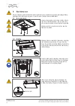
Page 17: ...an anti corro sion compound when remounting the fixing bolts Restore electric connection when the new fan has been mounted 6 2 Driptray Driptrays can be opened for inspection cleaning and maintenance...

Page 18: ...estore electrical connections 6 5 Driptray heater elements replacement Always disconnect power supply before handling heater elements To remove driptray heater elements remove central driptray and ope...

Page 19: ...notification Alfa Laval Anytime Spare parts Optigo CD 1 Fan motors 2 Defrost heater kits all heaters conn box fixing materials 3 Driptray left 4 Driptray right 5 Driptray central Spare parts can be s...

Page 20: ...www alfalaval com...

Reviews: