background image

Chapter 3 – Description of Controls

34

Wedge Reference Manual

STORE Button

The [

STORE

] button is used to permanently keep changes you make to a Program,

or to copy a Program to a different location. When pressed for the first time, the
[

STORE

] button will flash, to indicate that it is prepared to store the current

Program. At this point, you can choose to alter the Program’s name, and/or choose
a different location to store the Program into. When you’re ready to store, press the
[

STORE

] button a second time.

To store an edited Program:

Ê

Press [

STORE

].

The [

STORE

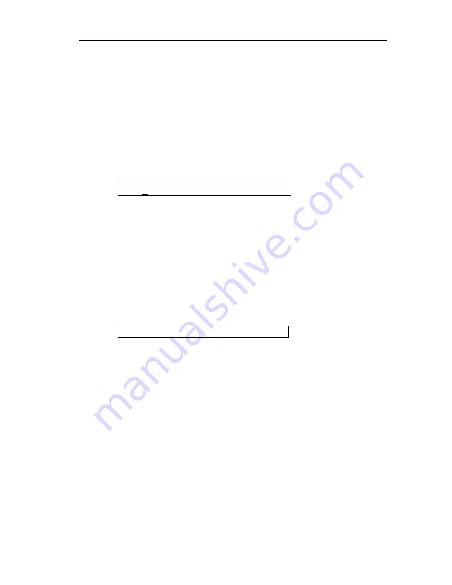
] button will flash, and the display will read:

Save XXX (nnnnnnnnnnnn)?

…whereas XXX is a Program location number from 00—127 in the User bank, and

nnnnnnnnnnnn is the Program’s name.

Ë

Use the [

VALUE

] knob to select which location (00—127) you wish to store the

selected Program into.

You can only store Programs into the User bank. If you select a Program from the

Preset bank and store it, you will automatically be taken into the User bank.

Ì

If desired, change the Program’s name.

See the section on the “A/B/C/D Buttons”, earlier in this chapter.

Í

Press [

STORE

] again.

The [

STORE

] button’s LED will momentarily flash quickly, while the display reads:

Prog nnnnnnnnnnnn Stored!

…whereby nnnnnnnnnnnn is the Program’s name. The [

STORE

] button will turn off

and the display will revert to wherever it was before [

STORE

] was pressed for the first

time.

COMPARE Button

The [

COMPARE

] button allows you to review what the Program sounded like

before you made any edits. This allows you to page through a program’s
parameters and see the previous values of any of your edits. You exit Compare
mode by pressing the [

COMPARE

] or [

PROGRAM

] button. Any edited parameters

will have the word “

EDITED

” next to the new value.

BYPASS Button

The [

BYPASS

] button switches the Wedge into Bypass mode. This mode allows you

to hear the “dry” signal without effects. If Dry Defeat (see UTIL mode, above) is
turned off and the Wedge is in Bypass mode, the input signal will be passed
through without effects. If Dry Defeat is turned on and Bypass is on, no signal will
pass through the unit.

Summary of Contents for Wedge

Page 1: ...ALESIS Wedge Reference Manual...

Page 2: ...rence guide when searching for specific information Chapter 4 Editing Programs A guided tour for programming typical single and multi effect applications Chapter 5 Overview of Effects A detailed look...

Page 3: ...2 Wedge Reference Manual...

Page 4: ...Wedge Reference Manual 3...

Page 5: ...to its Original Settings 14 Bypassing Effects 14 Storing and Naming Edited Programs 15 Connections 17 AC Power Hookup 17 Line Conditioners and Protectors 17 Audio Connections 17 Typical Applications 1...

Page 6: ...e Architecture of the Wedge 41 What is a Configuration 41 Single 41 Parallel 41 Dual Mono 41 Multi Chain 41 Reverb Effects 44 Large Hall 44 Hall Reverb 44 Room Reverb 44 Chamber 44 Ambience 44 Stereo...

Page 7: ...55 Low Pass Filter 55 Feedback Highpass and Lowpass Filters 55 Predelay 55 Wave 56 Triggered Flange 56 Width 57 Level 57 Motor Speed High Rotor Level 57 Effect Parameters 58 MIDI Applications 65 MIDI...

Page 8: ...Contents Wedge Reference Manual 7 Maintenance Service 74 Cleaning 74 Refer All Services to Alesis 74 Obtaining Repair Service 74 MIDI Implementation Chart 76 Specifications 77...

Page 9: ...Contents 8 Wedge Reference Manual GFX Front Rear Panel Diagram...

Page 10: ...commodate a number of applications whether you are connecting it with a mixing console or connecting an instrument directly into it Briefly described here are the basic connections to get you up and r...

Page 11: ...able to remove the direct dry signal from the outputs of the Wedge so that its output signal contains only the effected wet signal The dry signal may then be combined at the mixing console with the re...

Page 12: ...and Value Wheel Your input signal should make the meters go as far to the right as possible without clipping Automatic Input Level Settings The Wedge has the unique ability to automatically select th...

Page 13: ...rnal effect Programs Press the PROG button The PROG button will light Turn the VALUE knob to scroll through the 128 Preset and 128 User Programs Switching Between Preset and User Banks To instantly sw...

Page 14: ...effects like Reverb Delay or Chorus Delay Reverb Once you have identified what effects are used in the Program s Configuration you can then find the effect parameters more easily To edit a Program s e...

Page 15: ...ED will disappear Any changes you make are temporary until you store those changes into memory If the Program you are editing is in the Preset bank you must save the changes you ve made to a location...

Page 16: ...page available is selected Move the D slider to edit the Mix parameter The parameter will flash indicating it is selected for editing The Mix parameter s range is 000 100 Comparing an Edited Program...

Page 17: ...he PROG button three times This recalls the stored version of the selected Program number and the Configuration name in the display returns to all upper case letters Consequently any changes you had m...

Page 18: ...00 127 in the User bank and nnnnnnnnnnnn is the Program s name Use the VALUE knob to select which location 00 127 you wish to store the selected Program into You can only store Programs into the User...

Page 19: ...Chapter 1 Your First Session with the Wedge 16 Wedge Reference Manual...

Page 20: ...rong surges and spikes acting somewhat like fuses in that they need to be replaced if they ve been hit by an extremely strong spike Line filters These generally combine spike surge protection with fil...

Page 21: ...nd out to an amplifier or mixer input or from the stereo buss outputs of a mixer to a mix down tape machine or amplifier When used with a mono source the Wedge is placed between the source and the mix...

Page 22: ...ively if your console uses balanced 1 4 TRS connectors for the effects sends and returns like the Alesis Studio 32 you should use stereo phone cord TRS balanced cables for connection to the Wedge Inte...

Page 23: ...rcuitry of the Wedge can easily handle professional 4 dBu levels 20 dBu peaks while having enough input and output gain to interface with the lower 10 dBV signal levels of home and project recording s...

Page 24: ...er where you connect the output of the Wedge into the mixer you are in control of the balance between the mixer s channel inputs the uneffected signal being routed to the aux sends and the Mix and the...

Page 25: ...r mixer to use the Stereo In hookup described below Stereo In Stereo Out This connection is similar to the one described above However by utilizing two sends from the mixer we add one more cable from...

Page 26: ...fier and before the main fader essentially it is the same as connecting the source instrument or microphone into the Wedge before the mixer s channel input However some mixing console s inserts come a...

Page 27: ...represents the send which connects to the Wedge s input and black is the return which connects to the output Stereo If a stereo instrument such as a keyboard or sampler is con nected to two separate c...

Page 28: ...ll hear too much effect and no direct signal at all Avoiding Ground Loops In today s studio there are many opportunities for ground loop problems to occur These show up as hums buzzes or sometimes rad...

Page 29: ...d ground wire will cause a very loud hum D Keep all cables as short as possible especially in unbalanced circuits If the basic experiments don t uncover the source of the problem consult your dealer o...

Page 30: ...e It is not necessary to follow step 2 if you intend to only send information to the Wedge and do not need to receive information back from it Example If you only want to be able to recall Programs us...

Page 31: ...d the 128 Preset Programs are pre programmed at the factory and cannot be renamed Configuration This tells us what type of effect this Program is It can also tell you the order that the input signal s...

Page 32: ...ical value and bargraph will change in relation to the Value Slider s position The type of units will be shown as well dB mSec kHz etc A B C D and EDITED Indicators Each parameter in the selected page...

Page 33: ...rogram mode to select parameters for editing with the VALUE wheel on the current page When in Program mode pressing any of the A B C and D buttons will select the corresponding parameter A B C or D in...

Page 34: ...rameters in Edit mode The quickest way to edit a program on the Wedge is to press Edit and start moving the sliders You don t have to select a parameter before moving the slider just grab it and the p...

Page 35: ...arious functions which are not stored with the Effects Programs These include Page 1 Dry Defeat The Dry Defeat function when enabled removes the direct dry signal globally from all Programs simultaneo...

Page 36: ...will be recalled when certain program change numbers are received Note you can also use Bank Select messages to select Preset or User Programs see Chapter 6 for more information The first value in th...

Page 37: ...ten will change the input or output level by slightly over 3 decibels Below 040 the taper increases to approximately 6 dB per ten Auto Level When both the I O and TAP AUDITION buttons are pressed simu...

Page 38: ...ill automatically be taken into the User bank If desired change the Program s name See the section on the A B C D Buttons earlier in this chapter Press STORE again The STORE button s LED will momentar...

Page 39: ...ch connects to any MIDI compatible equipment such as a keyboard or another effects device It is provided for sending system exclusive commands for storing programs It also relays all messages received...

Page 40: ...Also the last 28 Programs in the User bank 100 127 have been left blank so you have some place to store your new Programs into To select a Configuration Press PROG Use the VALUE knob to select a Prog...

Page 41: ...Chapter 4 Editing Programs 36 Wedge Reference Manual Now you can start editing the Program s parameters and having some real fun...

Page 42: ...e names will appear at the top of the display above their value settings Parameter Values and Bar Graphs Each parameter in the selected page is shown with both a numerical value and a bargraph When a...

Page 43: ...i e Lezlie Speed Slow Fast simply pressing one of the A B C or D buttons will switch the value Using Online Help The Wedge has built in online help to assist you in identifying parameter functions fro...

Page 44: ...the first character of the Program s name Use the C and D buttons to move the cursor left and right respectively through the 12 character fields in the Program s name Use the VALUE knob to change the...

Page 45: ...Decay and LPF parameters The Decay time A Slider dictates the size of the room and the LPF emulates the wall surfaces To simulate a large castle chamber with a few tapestries and other soft surfaces w...

Page 46: ...drapes and couches to the hall For this room I ll leave Low Damping off and set my High Damping for 2 14kHz Remember that if you set the High Damping higher than the input LPF it will do almost nothi...

Page 47: ...ting Programs 42 Wedge Reference Manual Finally I ll leave the Depth at the default 60 The resulting program should sound like a large darkened church with plenty of character for orchestral instrumen...

Page 48: ...re summed internally before being fed into the effect so it doesn t really matter which input is used The left and right inputs need to be used only if you are using the Wedge inline between a stereo...

Page 49: ...ght output The Configurations with a in their name have independent control of the two effects while CHORUS FLANGE has two separate mono signal paths that are controlled by synchronized parameters to...

Page 50: ...t the following effect receives at its input s Example It is possible to use the Delay Room Configuration where effect 1 is a mono delay and effect 2 is a reverb and have only the dry uneffected signa...

Page 51: ...e sound of a medium size studio room It has a quick attack and programmable reflections It sounds good on drums keyboards and guitars Chamber Similar to the Room Reverb this algorithm simulates a poli...

Page 52: ...Nonlinear This reverb effect s direction can be set either forwards or backwards Selecting the forward direction provides a classic Gated digital reverb sound Selecting the reverse direction gives you...

Page 53: ...z and attenuates all frequencies above this value by 6dB per octave The lower the setting the less high frequencies are allowed to pass thru to the reverb effect The LPF simulates the reflectivity of...

Page 54: ...a bit of the Reverb before the Pre Delayed Reverb sounds making the delay less apparent Density Density controls how smooth the reverb decay and early reflections sound When set for very low values th...

Page 55: ...set for 8kHz and the High Damping parameter is set above 8kHz you won t hear much of a change from this parameter This is because the high frequencies have already been rolled off so there s nothing l...

Page 56: ...ds over to the other side Reverberation Swirl This parameter is very useful for adding randomness to the decay of a reverb when set to a low value When set to a high value it creates a more dramatic c...

Page 57: ...and low cutting The delay time can be adjusted separately by 100ms 10ms and 1 ms increments Ping Pong Delay So called because the output bounces from left to right in stereo with the speed determined...

Page 58: ...Delay time will change to match the tempo of this source Feedback The Feedback parameter controls the regeneration of the delay If feedback is set for 0 you will only hear one delay If it is set for...

Page 59: ...er which effects the delayed signal Like the Tremolo effect you can set the delay time to 000mS for a simple autopan effect or use it with the delay for panning delays Rate controls the speed and Dept...

Page 60: ...he signal into three parts with a dry signal and a separate Detuning section for both left and right channels offset from one another The detuning is further effected by being modulated by an LFO low...

Page 61: ...larly panned in the Outputs Voices 1 2 3 and 4 are panned from hard Left to Hard Right Chorus Chorus This is a dual mono configuration with two independent mono Chorus Flangers Even though the configu...

Page 62: ...ince the Wedge is digitally simulating the flanging effect it normally cannot provide the through zero effect The Thru0 parameter found in the Wedge s flanging effects lets you create the appearance o...

Page 63: ...whenever it is triggered and then runs until the next time you trigger it This function is controlled by three parameters Trig This selects which input to monitor to begin triggering The choices are O...

Page 64: ...ameters control the sound of the rotary speaker simulation Motor turns the spinning effect on or off but does not bypass the effect it will still be phased and filtered with the rotor on frozen in its...

Page 65: ...p OFF 029 4 3 HDamp 029 4 3 OFF Swirl 00 50 Depth 000 100 4 Spread 000 500 Shape 0 4 Level 00 99 5 Gate OFF 001 100 Hold 000 500 Rel 000 500 Mix 000 100 STEREO ROOM 1 Decay 00 7 8 LPF 029 4 3 OFF PDly...

Page 66: ...000 100 PLATE 1 Decay 59 6 2 LShlf 000 255 HPF OFF 029 4 3 LPF 029 4 3 OFF 2 Dens 000 100 Diff 000 100 PDly 000 250 PMix 000 100 3 LDamp OFF 029 4 3 HDamp 029 4 3 OFF Swirl 00 50 Depth 000 100 4 Gate...

Page 67: ...k 99 99 2 LoCut OFF 029 4 3 HiCut 029 4 3 OFF Dens 000 100 3 Rate 00 47 Depth 000 250 TremR 00 47 TremD 000 100 4 PanR 00 47 PanD 000 100 Mix 000 100 PINGPONGDLY 1 100ms 0 24 10ms 0 9 1ms 0 9 Fdbk 00...

Page 68: ...1 000 250 PDly2 000 250 PDly3 000 250 PDly4 000 250 6 Width 99 99 Lvl2 00 99 Lvl3 00 99 Mix 000 100 CHORUS CHORUS 1 Rate 00 47 Depth 000 250 Fdbk 99 99 PDly 000 250 2 LPF 029 4 3 OFF FBHPF OFF 029 4 3...

Page 69: ...99 PDly 000 250 3 LPF 029 4 3 OFF FBHPF OFF 029 4 3 FBLPF 029 4 3 OFF CMix 000 100 4 Decay 00 7 8 LPF 029 4 3 OFF PDly 000 250 PMix 000 100 5 Dens 000 100 Diff 000 100 Gate OFF 010 500 RMix 000 100 RO...

Page 70: ...ix 000 100 ROOM CHORUS 1 Decay 00 7 8 LPF 029 4 3 OFF PDly 000 250 PMix 000 100 2 Dens 000 100 Diff 000 100 Gate OFF 010 500 RMix 000 100 3 L Rate 00 47 Depth 000 255 Fdbk 99 99 PDly 000 250 4 R Rate...

Page 71: ...s for use with the realtime modulation capabilities in the Wedge To set the Wedge s MIDI channel Press UTIL The UTIL button will light Continue pressing the UTIL button until page 2 is selected The di...

Page 72: ...User bank via MIDI by sending a Controller 0 message immediately followed by a program change message A Controller 0 with a value of 0 will select the Preset bank while a value of 1 or higher up to 12...

Page 73: ...am Buffer or the Program Change Table Table Set the receiving MIDI device to receive or record the MIDI information about to be sent from the Wedge Press the flashing STORE button to transmit The STOR...

Page 74: ...ile Modulator Y controls the Reverb s wet dry mix Keep in mind that both Modulator X and Y can be assigned to the same MIDI message Therefore a single MIDI source can modulate two different parameters...

Page 75: ...ELAY Feedback Wet Dry Mix MULTI TAP Master Feedback Wet Dry Mix DELAY DELAY Delay 1 Feedback Delay 2 Feedback CHRS FLANGE Wet Dry Mix Depth QUAD CHORUS Wet Dry Mix Depth CHRS CHRS Chorus 1 Wet Dry Mix...

Page 76: ...value but it has nowhere to go If you bring the Mix parameter all the way down to 0 the mod wheel will have total control move the mod wheel all the way up and down to move the Mix parameter from dry...

Page 77: ...fferent from Continuous Controller messages in several ways To decide which method of control is best for your application consider the following Exclusive control Sysex messages from the Wedge may on...

Page 78: ...Chapter 6 MIDI Applications 72 Wedge Reference Manual...

Page 79: ...ected then press D to turn off Dry Defeat Bypass function is on with effect s MIX parameter set to 0 Use EDIT to locate the effect s MIX parameter and set it to 100 if more than one effect is used in...

Page 80: ...ing current technology and should provide years of trouble free use However should problems occur DO NOT attempt to service the unit yourself Static sensitive digital devices are enclosed which may be...

Page 81: ...warranty Tape a note to the top of the unit describing the problem include your name and a phone number where Alesis can contact you if necessary as well as instructions on where you want the product...

Page 82: ...er X O Control Change 0 119 X O Controller 0 used as Bank Select 0 Preset 1 127 User Prog Change True X O 00 127 00 127 System Exclusive O O System Common Song Pos Song Sel Tune X X X X X X System Rea...

Page 83: ...tereo 500k channel mono A D D A Conversions Processor Speed 6 MIPs million instructions per second Processor Memory 64K x 16 bits A D converter 18 bit Sigma Delta 128 times oversampling D A converter...

Page 84: ...ssing resolution 24 bit accumulator Delay memory 5499 milliseconds 5 49 seconds Reverb effects Large Hall Hall Reverb Stereo Room Room Reverb Chamber Ambience Large Plate Plate Nonlinear Delay effects...

Reviews: