Aleo P23 Installation Manual Download Page 11

aleo solar GmbH

 | Marius-Eriksen-Straße 1 | 17291 Prenzlau | Germany | 

[email protected]


Installation manual Ver. 4.8, 05/2021, en   

Page 11 of 20


9.2.1 

Weather protection 

EIS 


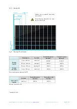
Lay  the  cables  so  that  they  exit  the  junction  box  from  below. 
This prevents water, which runs along the cable, from collecting 
at the point where the cables exit the junction box. 


For  modules  mounted horizontally,  lay the  cables in  a  U-form 
away from the junction box (see fig. 2). 


Modules mounted vertically do not usually need any additional 
adjustments. 


Fig. 2 

U-form  cables  at  the  junction  box  for  a  horizontally 
mounted module 

 
Lay cables carefully to protect against damage from: 

-


direct environmental factors, such as precipitation, 

-


movement (e.g. from wind), 

-


indirect environmental factors, e.g. snow or ice, which slip 
down behind the modules and 

-


chaffing  on  the  insulation  due  to  the  cable  moving  (e.g. 

from wind or ice). 


9.3  Potential equalization (earthing) of module frames 


Local regulations may specify potential equalisation (earthing). 


When  earthing  the  module  frame,  establish  a  safe  electrical 
connection to the earth potential or earthed sub-structure. 


Observe the requirements and recommendations of the invert-
er manufacturer, as well as insurance policies. 


The  module  frames  are  made  of  aluminium.  When  mounting 

onto other materials, take suitable measures to prevent electric 
corrosion, e.g. by using a coating. 

Potential equalization does not serve as lightning protection. Light-
ning protection may be necessary in addition


to potential equaliza-

tion. 

9.4  Lightning protection 

 
WARNING! 

Absence  of  or  inadequate  lightning  protection:  Risk  of  fire  or 
electric shock! 


Leave  the  planning  and  installation  of  the  external,  and  if  re-
quired internal, lightning protection to be always carried out by 
qualified technicians. 


It is essential to integrate an arrestor for connecting the light-

ning rod with the lightning protection. This ensures the safety 
and reliability of the lightning protection as well as the photo-
voltaic system.  


Do not under  any  circumstances  include  the  module  frame  or 

its earth as an active part of the lightning protection (e.g. as a 
lightning arrestor). 


If  you  earth  the  module  frame,  the  only  task  of  this  earth  is  the 

potential equalisation between the module frame and the support-
ing structure. 


9.5  Parallel and serial connection 

PV modules of the same type can be connected in parallel. The PV 
modules  in  this  series  are  fundamentally  designed  for  series  con-

nection. 


Only use PV modules of the same type and output for parallel 

connection.  Take  measures  for  over-current  protection  (e.g. 
line fuses) if necessary. Never exceed the specified reverse cur-

rent loadability of the PV modules. Maximum number of mod-
ule  strings that are  allowed  to  be switched  in parallel:  2  (fuse 
rating / (short-circuit current x1.25) + 1) 


Make sure that only PV modules with the same amperage (I

MPP

are  interconnected  for  series  connection  and  make  sure  that 
the voltages of strings connected in parallel are the same. Even 
at  low  temperatures,  never  exceed  the  maximum  permissible 

system  voltage  of  the  PV  modules.  Maximum  number  of  PV 
modules  that  are  allowed  to  be  switched  in  series:  maximum 

system  voltage  /  (open  circuit voltage  x 1.25),  with respect to 
the temperature coefficient. 


Make sure that the number and connection of the PV modules 
match the electrical values specified by the devices connected 
to the photovoltaic system. 


Make sure that the polarity is correct. 


Summary of Contents for P23

Page 1: ...8 05 2021 en Page 1 of 20 INSTALLATION MANUAL For the aleo modules with standard frame 42mm X63 X61 X83 X81 with standard frame 35mm P23 with frame for the roof integration S83sol S81sol Please read...

Page 2: ...l BE Wenst u deze handleiding in het Nederlands te ontvangen neem dan contact op met de klantenservice van aleo solar zie hoofdstuk 2 2 2 Product support 2 1 Detailed information In addition to this R...

Page 3: ...afety precautions 8 8 3 Improper mounting 8 8 4 Intervals 8 8 5 Avoiding seals 9 8 6 Clearance under the modules 9 8 7 Shadowing 9 9 Electrical installation 10 9 1 Connectors 10 9 2 Laying the string...

Page 4: ..._________ WEIS NOTE indicates a potentially dangerous situation which can cause material damage if not avoided 4 2 Notes on modules The following symbol is attached to the modules If this symbol also...

Page 5: ...perience conditions that produce more current and or voltage than reported at standard test conditions 1 Accordingly the values of ISC and UOC marked on the modules should be multiplied by a factor of...

Page 6: ...les WARNING Damaged insulating back sheet Risk of electric shock and burns Avoid any contact with the back of the module with sharp or pointed objects Ensure that the back sheet remains undamaged 7 Pr...

Page 7: ...voltages possible even when the photovoltaic generator is disconnected if the generator is earthed Severe or fatal inju ries from electric shock If the circuit of your photovoltaic generator is earth...

Page 8: ...ield and re sults in loss of warranty rights Do not attach the modules by welding The temperatures cre ated in the process can cause delamination micro fissures and loss of yield and results in loss o...

Page 9: ...rtunity to affect the shadowing then take another site into consideration or only plan with the non shadowed parts of your site when you configure your photovoltaic generator 8 7 2 Effects of shadowin...

Page 10: ...4 connectors are referred to as MC4 in the data sheet 9 2 Laying the string cables CAUTION Brittle fractures in junction boxes due to contact with unsuitable connection cables Risk of fire Only use co...

Page 11: ...lectric shock Leave the planning and installation of the external and if re quired internal lightning protection to be always carried out by qualified technicians It is essential to integrate an arres...

Page 12: ...both short and long sides Fig 7 Not permissible clamp arrangement 2 c Protruding clamps d Opposing clamps have different distances to the module corners e Asymmetrical clamps on the short side 10 2 2...

Page 13: ...s A load can be a pressure load as well as a suction load Loads from snow and wind are grouped into several levels which need to be considered wherever the module is installed Higher load levels make...

Page 14: ...test load Clamping long side 0 mm 458 mm Load level I 2400 Pa 2400 Pa 120 mm 458 mm Load level II 3900 Pa 2400 Pa 220 mm 458 mm Load level III 5400 Pa 2400 Pa 220 mm 300 mm Load level IV 8000 Pa 5400...

Page 15: ...0 mm 293 mm Load level I 2400 Pa 2400 Pa 120 mm 293 mm Load level II 3900 Pa 2400 Pa 180 mm 293 mm Load level III 5400 Pa 2400 Pa 180 mm 220 mm Load level IV 8000 Pa 5400 Pa Clamping short side 0 mm...

Page 16: ...t load Permissible suction test load Clamping long side 0 mm 458 mm Load level I 1400 Pa 1400 Pa 220 mm 458 mm Load level II 3900 Pa 2400 Pa 220 mm 300 mm Load level III 5400 Pa 2400 Pa Clamping short...

Page 17: ...om trees or neighbouring houses 11 1 2 Inspection of the documentation and drawings check the module string plan 7 check the inverter s status reports determine and archive the annual output create an...

Page 18: ...of deposits is avoided 12 This prevents mechanical tension in the glass and ensures the module a longer service life For stubborn patches of dirt use the following to help Isopropanol aleo solar recom...

Page 19: ...precautions and chap 6 2 1 Electrical safety precautions 11 5 2 System parts For repairing other system parts e g substructure connection boxes contract authorised technicians to do the work or contac...

Page 20: ...Stra e 1 17291 Prenzlau Germany info aleo solar com Installation manual Ver 4 8 05 2021 en Page 20 of 20 Aleo solar GmbH Marius Eriksen Stra e 1 17291 Prenzlau Germany Contact 49 0 3984 8328 0 info al...

Reviews: