173cc 4 Stroke Petrol Lawn Mower
AFTER SALES SUPPORT
e-mail: [email protected]
1800 909 909
MODEL No.: DM46E3P-D173 • 02/2018 • 59085
(toll free)
AFTER SALES SUPPORT
(toll free)
173cc 4 Stroke Petrol Lawn Mower
e-mail: [email protected]
1800 909 909
MODEL No.: DM46E3P-D173 • 02/2018 • 59085
24
25
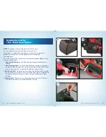
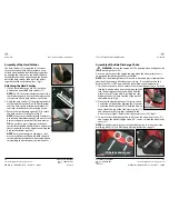
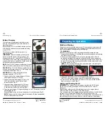
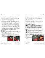
Assembly of the Hard Catcher
The hard catcher (13) is supplied in 2 sections.
Locate the top half of the hard catcher on top
of the bottom half and interlock them together
by aligning the clips on the top half of the hard
catcher into the raised ridge around the bottom
half of the hard catcher, then push the halves
together until they click into place. (Fig J)
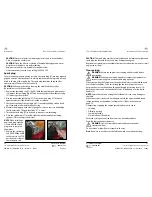
Attaching the Hard Catcher
1. Lift the rear discharge guard (16) in order to
position the assembled hard catcher (13).
NOTE: Do NOT ever start the lawn mower if the
rear discharge guard does not fully return to the
close position if the hard catcher is not fitted.
2. Apply the hard catcher (13) by aligning the hard
catcher attachment bar (2) on the hard catcher
over the hard catcher attachment bracket (15)
centrally so the hard catcher is sitting evenly.
3. Release the rear discharge guard (16) to secure
the hard catcher (13) into place. (Fig K)
NOTE: Always empty the hard catcher before it
has reached maximum capacity, otherwise it will
decrease the performance of the lawn mower.
TIP: Do not leave grass clippings in the hard
catcher for extended periods of time, and ensure
there is no build up in the ridges connecting the
hard catcher halves together.
NOTE: Ensure that any grass clippings or dirt
are removed from the channel within the hard
catcher attachment bracket when removing and
re-attaching the hard catcher in between uses.
J.
K.
Assembly
Assembly
Assembly of the Side Discharge Chute
WARNING: Ensure the engine is NOT operating when fitting the side
discharge chute (20).
Do not operate or have the engine running when the side ejector cover is
opened and the discharge chute is not fitted.
NOTE: The side discharge chute (20) is used to distribute grass clippings from
the side of the mower while the mower is in use. To use this function, the
hard catcher (13) is NOT required to be assembled on the lawn mower.
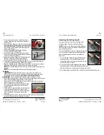
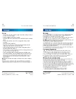
1. This side ejector has a lock to ensure it is secured when not in use. Push the
lock tab in an upwards direction to disengage the
lock, then using your other hand, lift up the side
ejector cover (21) to be able to position the side
discharge chute (20) onto the side of the deck of
the lawn mower. (Fig L)
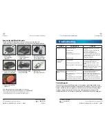
2. Place the side discharge chute (20) into position
on the side of the deck by aligning the 2 top tabs
on the side discharge chute (20) with the bars on
each side at the top of the side ejector cover (21),
and then place the 2 top tabs underneath the
bars to secure (Fig M). Release the side ejector cover (20). (Fig N)
3. To remove the side discharge chute (20), raise the side ejector cover (21),
and remove the side discharge chute (20). Lower / release the side ejector
cover (21).
NOTE: For the best performance in “side discharge chute” mode, insert the
mulching block (14). See Mulch and Mowing instructions page 27.
Raise ejector cover
L.
N.
M.
Slide tabs under bars


