background image

2024 series Tooling 

(HK1077)


Alcoa Fastening Systems

7

S

ERVICING


THE


TOOL

GENERAL

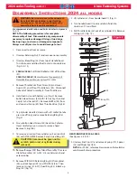
1.   The effi ciency and life of any tool depends 

upon proper maintenance. Regular inspection 
and correction of minor problems will keep tool 
operating effi ciently and prevent downtime. The 
tool should be serviced by personnel who are 
thoroughly familiar with how it operates.

2.  A clean, well-lighted area should be available for 

servicing the tool. Special care must be taken 
to prevent contamination of pneumatic and 
hydraulic systems.

3.   Proper hand tools, both standard and special, 

must be available.

4.   All parts must be handled carefully and 

examined for damage or wear. Always replace 
Seals, when tool is disassembled for any reason. 
Components should be disassembled and 
assembled in a straight line without bending, 
cocking, or undue force. Disassembly and 
assembly procedures outlined in this manual 
should be followed.

5.  

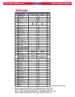
Service Parts Kit 2024KIT

 includes consumable parts 

and should be available at all times. Other 
components, 

as experiece dictates, should also be available.

DAILY

1.  If a Filter-Regulator-Lubricator unit is not being 

used, uncouple air disconnects and put a few 
drops of Automatic Transmission Fluid or light 
oil into the air inlet of the tool.  If the tool is in 
continuous use, put a few drops of oil in every two 
to three hours.

2.  Bleed the air line to clear it of accumulated dirt or 

water before connecting air hose to the tool. 

3.  Check all hoses and couplings for damage or air 

leaks, tighten or replace if necessary.

4.  Check the tool for damage or air/hydraulic leaks, 

tighten or replace if necessary.

5.  Check the nose assembly for tightness or 

damage,  tighten or replace if necessary.

6.  Check stroke periodically,  if stroke is short add 

oil.

WEEKLY

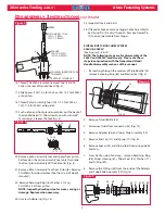
1. Disassemble, clean,  and reassemble nose 

assemblies per applicable nose assembly 
instructions.

2.  Check the tool and all connecting parts for 

damage or oil/air leaks, tighten or replace if 
necessary.

as experiece dictates, should also be available.

WARNING: Inspect tool for damage or 
wear before each use. Do not operate if 
damaged or worn, as severe personal 
injury may occur.

O

PERATING

 I

NSTRUCTIONS

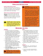
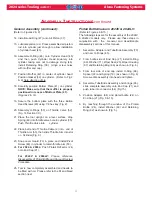
BLIND FASTENER INSTALLATION:

The fastener may be placed either in the work hole or in 
the end of the nose assembly. In either case, tool and nose 
assembly must be held against work and at right angles to 
it. Depress trigger and hold it depressed un  l fastener is 
installed and pintail breaks. Release trigger.

MAGNA GRIP® FASTENER INSTALLATION:

Place pin in work-hole and place collar over pin. See 

WARNINGS

. (If collar has only one tapered end, that 

end 

MUST

 be out toward tool.) Hold pin in hole. Push 

nose assembly onto pin protruding from collar un  l anvil 
touches collar. Press trigger and hold down un  l collar is 
swaged and pintail breaks. Release trigger.

WARNINGS: 
Inspect tool for damage or wear before 
each use. Do not operate if damaged or 
worn as severe personal injury may occur. 

Pulling on a pin (fastener) without a collar, 
or with collar chamfer against workpiece, 
may result in pin becoming a high speed 
projectile when pin grooves are stripped 
or pintail breaks off. Fatal or severe injury 
is possible to anyone in the pins line of 
fl ight. This includes pins that ricochet.

Broken pintails eject from defl ector with 
speed and force. Be sure pintail defl ector 
is directed safely away front operator 
or the personnel in the area. Ejecting 
pintails striking anyone may cause serious 
personal injury. For Models 202B and 
202V, pintail bottles must always be used. 
Replace damaged pintail defl ectors and 
bottles as serious personal injury may 
occur from pintails when using these 
defective parts.

CAUTION: Remove excessive gap from 
between sheets for enough of the pintail 
to stick out of the collar for all of the 
jaw teeth to grip into the pintail grooves.
 
Jaws not fully gripping pintail grooves 
will be stripped or broken

.

Summary of Contents for Huck 2024 Series

Page 1: ...04 24 2013 HK1077 INSTRUCTION MANUAL 2024 SERIES PNEUDRAULIC INSTALLATION TOOLS ALL MODELS...

Page 2: ...2024 series Tooling HK1077 Alcoa Fastening Systems 2...

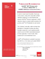
Page 3: ...ium strength blue threadlocker is designed for locking and sealing threaded components It can be applied smoothly and will now be the HUCK recommended standard for these applications For best results...

Page 4: ...This page is intentionally blank...

Page 5: ...N FOR USE 6 OPERATING INSTRUCTIONS 7 SERVICING THE TOOL GENERAL 7 DAILY 7 WEEKLY 7 DISASSEMBLY GENERAL 8 HEAD HANDLE 8 9 PINTAIL BOTTLE VACUUM SYSTEM 9 ASSEMBLY HEAD HANDLE 10 GENERAL 10 11 PINTAIL BO...

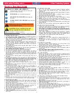
Page 6: ...unsuitable postures as it is likely for these not to allow counteracting of normal or unexpected tool movement 8 If the assembly power tool is fixed to a suspension device make sure that fixation is s...

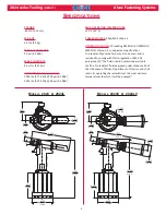
Page 7: ...76 kN 90 psi 6 2 BAR 3549 lbs 15 79 kN 80 psi 5 5 BAR MAX OPERATING TEMPERATURE 125 F 52 C POWER SOURCE 90psi MAX shop air HYDRAULIC FLUID ATF mee ng DEXRON III DEXRON IV MERCON Allison C 4 or equival...

Page 8: ...is shipped with a plas c plug in the air inlet connector The connector has 1 4 18 female pipe threads to accept the air hose fi ng Quick disconnect fi ngs and 1 4 inside diameter air hose are recommen...

Page 9: ...tructions 2 Check the tool and all connecting parts for damage or oil air leaks tighten or replace if necessary as experiece dictates should also be available WARNING Inspect tool for damage or wear b...

Page 10: ...let to take pressure off ring and remove Retaining Ring 38 Fig 2 8 Screw Button Head Screws 40 back into Cylinder Head Carefully pry on screws to remove head Remove O ring 46 9 To remove air piston fr...

Page 11: ...Assembly 2 by driving Pin 4 out with punch Remove Dowel Pin 3 to disconnect cable from trigger PINTAIL BOTTLE VACUUM SYSTEM 2024V 2024LV See Figures 5 6 15 NOTE The following steps are for disassembly...

Page 12: ...1 4 for 2024L 2024LV onto Piston 6 Slide complete Gland Assembly and Wiper Seal 9 onto Piston 6 7 Install assembled components in gently from rear of tool using a press as shown in Fig 8 8 Remove Pist...

Page 13: ...Arm into slot on Cylinder Fig 9 23 Snap Lever Guard 73 in place and install Pivot Screw 48 in cylinder to retain throttle arm 53 24 For 2024 2024L Push Pintail Deflector 24 onto End Cap 21 For 2024V 2...

Page 14: ...Top off fluid in fill port install bleed plug and tighten Step 7 Connect airline to tool and measure the tools stroke refer to the Measuring Tool Stroke section If stroke is less than specified remov...

Page 15: ...Figure 12 Figure 13 2024 2024V Step 1 Cycle Piston all the way forward and measure X Step 2 Cycle and hold piston back and measure Y Step 3 Stroke Y X 2024L 2024LV Step 1 Cycle Piston all the way forw...

Page 16: ...2 3 4 5 6 7 8 9 10 11 12 14 15 16 17 18 19 21 22 23 24 25 34 35 36 37 38 39 40 41 42 43 44 45 46 47 48 SECTION A A 6 HUCK INTL INC 1 CORP DR KINGSTON N Y 12401 USA SCFM L M GPM BAR PSI 61 60 59 M A X...

Page 17: ...2024 series Tooling HK1077 Alcoa Fastening Systems 15 ASSEMBLY DRAWING Refer to Parts Lists on following pages 54 A A 21 70 22 68 69 23 67 66 65 64 63 62 71 PARTIAL SECTION AA 24 6 FIG 15...

Page 18: ...RNING Sticker 590240 1 1 21 End Cap 127742 125862 1 22 Spacer 507323 125866 1 23 Wiper Seal 507351 1 24 Pintail Deflector 124210 n a 1 Pintail Bottle n a 123772 25 Gland Assy 125742 1 26 Gland Housing...

Page 19: ...ng 500779 2 58 O Ring 500778 1 59 CE Sticker 590350 1 60 MAX Pressure and Flow Sticker 590351 1 61 HUCK Address Sticker 590347 1 62 Retaining Ring n a 501007 1 63 Washer n a 506628 1 64 Adapter n a 12...

Page 20: ...eplace if necessary 5 Hydraulic fluid leaks at rear of Pull Piston 6 a Worn or damaged piston Polyseal 18 replace if necessary 6 Hydraulic fluid leaks at front of Pull Piston 6 a Worn or damaged Front...

Page 21: ...ty period for tooling other items nonstandard or custom products described above and Huck shall inspect products for which such claim is made TOOLING PART S AND OTHER ITEMS NOT MANUFACTURED BY HUCK HU...

Page 22: ...33 1 30 27 9500 FAX 33 1 34 66 0600 A Global Organization Alcoa Fastening Systems AFS maintains company offices throughout the United States and Canada with subsidiary offices in many other countries...

Reviews: