3-5
Connecting to a Power Source
3
3.
If installing a single switch only, go to “Connecting to a Power Source” at the
end of this chapter.
4.
If installing multiple switches, attach four adhesive feet to each one. Place each
device squarely on top of the one below, in any order.
Installing an Optional SFP Transceiver into the Switch
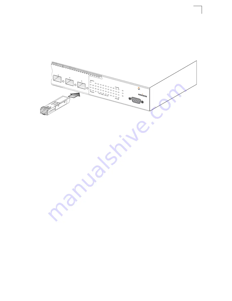
Figure 3-5. Inserting an SFP Transceiver into a Slot
To install an SFP transceiver, do the following:
1.
Consider network and cabling requirements to select an appropriate SFP
transceiver type.
2.
Insert the transceiver with the optical connector facing outward and the slot
connector facing down. Note that SFP transceivers are keyed so they can only
be installed in one orientation.
3.
Slide the SFP transceiver into the slot until it clicks into place.
Note:
SFP transceivers are hot-swappable. The switch does not need to be powered off
before installing or removing a transceiver. However, always first disconnect the
network cable before removing a transceiver.
Connecting to a Power Source
To connect a device to a power source:
1.
Insert the power cable plug directly into the receptacle located at the back of
the device.
Console
1
3
5
7
9
11
13
15
17
19
21
23
1000=Yellow
100=Green
10=Flash
ing Green
Power
RPU
Diag
2
4
6
8
10
12
14
16
18
20
22
24
Link
Act
Link
Act
1000=Y
ellow
100=G
reen 10=Flashing
Green
Console
1
3
5
7
9
11
13
15
17
19
21
23
1000=Green
10/100=Y
ellow
Power
RPU
Diag
2
4
6
8
10
12
14
16
18
20
22
24
Link/
Act
FDX
Link/
Act
FDX
1000=Green
10/100=Y
ellow
6300-24
OmniSta
ck
Console
1
3
5
7
9
11
13
15
17
19
21
23
1000=Green
10/100=Y
ellow
Power
BPS
Diag
2
4
6
8
10
12
14
16
18
20
22
24
Link/
Act
FDX
Link/
Act
FDX
6300-24
OmniSta
ck
Summary of Contents for OmniStack 6300-24
Page 1: ...Part No 060190 10 Rev A December 2003 OmniStack 6300 24 Getting Started Guide...
Page 4: ......
Page 14: ...xii Tables...
Page 16: ...xiv Figures...
Page 36: ...3 8 Installing the Switch 3...
Page 48: ...B 4 Cables B...
Page 54: ...Glossary Glossary 4...
Page 57: ......
Page 58: ...060190 10...


