background image

The antennas transmit and receive radio signals. This performance is also affected by environment factors (such as
the distance between the device and the base station), physical obstacles and other interferences due to radio fre-
quencies (RF).

For optimum coverage, follow these steps:

• Whenever possible, place the antenna where there are no physical obstacles. Obstacles between the antenna and

the base station degrade the wireless signal. Place the antenna above ground level facing the nearest base sta-
tion.

• The density of materials also affects the antennas. Place them away from all types of walls, metal screens, mirrors,

etc.

• Do not place the antenna near columns, which may throw shadows and reduce the coverage area.

• Keep the antenna away from metal ducts (such as canalization, air-conditioning etc.).

• Please bear in mind that other wireless devices such as telephones, microwaves, etc., can temporarily interfere

with the quality of the radio signal.

• We do not recommend installing antennas near, or between, racks containing communication devices, computers,

etc. Use an extension cable and place the device outside.

The following recommendations are applicable to all wireless devices:

• Do not touch or move the antenna while the device is transmitting or receiving.

• Do not touch any equipment containing devices that radiate, where the antenna is very close to (or touching) any

exposed part of the body (particularly the face and eyes) while transmitting.

• Do not install the device in areas where the atmosphere is potentially explosive.

• Wireless devices can cause interferences in other devices. Do not use the device in areas where medical equip-

ment is installed.

• To ensure the R&TTE 1999/5/EC directive is complied with, the device must be at least 15 cm away from a per-

son’s body when operating.

3.6.5 Wireless LAN Antenna Connection (Wi-Fi connectors)

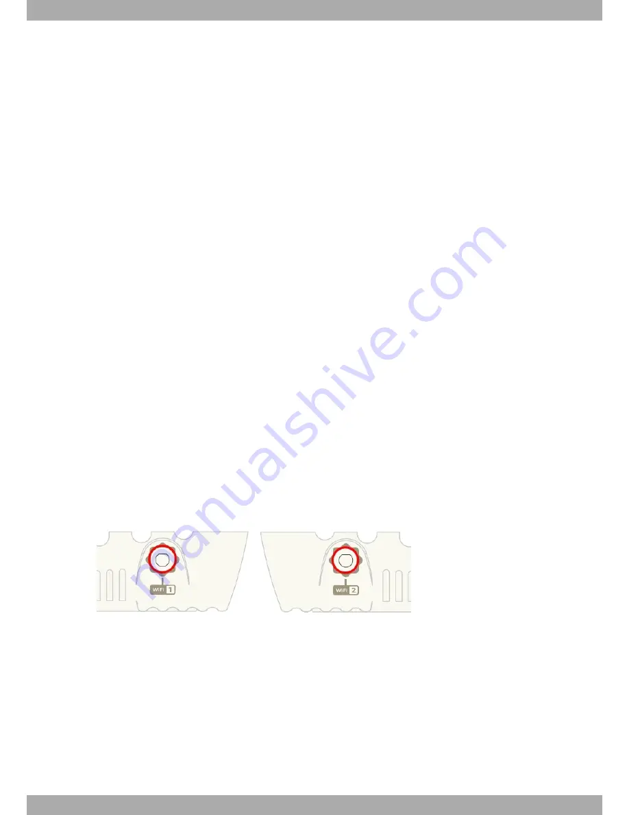
The OA5710V router has two RF antenna connectors for an external antenna to improve the quality of the signal re-
ceived and transmitted by the Wireless LAN module.

This module is internal and can be activated by purchasing the corresponding software license. To assemble and
disassemble the antennas provided with the device, just screw them into the connectors, labeled

Wi-Fi

, which are

located on both lateral panels of the router.

Fig. 16:

Wi-Fi Antenna 1

and Fig. 18:

Wi-Fi Antenna 2

3.6.6 Connecting a 3G USB device (USB connector)

The OA5710V has a USB HOST 2.0 Type A connector interface that allows 3G USB modems to be connected. The
interface can be activated by purchasing the corresponding software license.

Alcatel-Lucent Enterprise

3 Components and Power Supply

OA5710V Router

15

Summary of Contents for OA5710V

Page 1: ...OA5710V Router Installation Manual Copyright ALU Dm567 I Version 9 3 9 2017 Alcatel Lucent Enterprise Alcatel Lucent Enterprise Manual OA5710V Router 1...

Page 2: ...offers no warranty whatsoever for information contained in this manual Alcatel Lucent Enterprise is not liable for any direct indirect collateral consequential or any other damage connec ted to the de...

Page 3: ...g 3 Chapter 3 Components and Power Supply 4 3 1 Components 4 3 1 1 Front Panel 4 3 1 2 Rear Panel 4 3 1 3 Side Panels 5 3 1 4 Underside Panel 5 3 1 5 Top Panel LEDs 6 3 2 Mounting in rack 7 3 2 1 Stan...

Page 4: ...Statement 24 4 10 1 Federal Communications Commission Interference 24 4 10 2 FCC Radiation Exposure Statement 24 4 10 3 FCC Part 68 Notice 25 4 11 IC Statement 25 4 11 1 CAN ICES 3 B NMB 3 B 25 4 11...

Page 5: ...N Interface 32 A 4 7 USB Interface 32 A 4 8 Configuration Interface 32 A 4 9 Power Supply 32 A 4 10 External Power Supply 33 A 4 11 Dimensions and weight 33 A 4 12 Environmental Specifications 33 Appe...

Page 6: ...Table of Contents Alcatel Lucent Enterprise iv OA5710V Router...

Page 7: ...supply requirements Elements you can connect to the device while it is running Installation and removal procedures for modules and power supplies A description of the device LEDs and connectors Troubl...

Page 8: ...Pacific 65 6240 8484 Web support esd alcatel lucent com Email ebg_global_supportcenter al enterprise com 1 8 Related Documentation ALU Dm741 I ADSL VDSL2 ALU Dm748 I Software Updating ALU Dm781 I Cell...

Page 9: ...10 2 1 2 Hardware Monitoring The only way to monitor the OA5710V router hardware is through the LEDs panel The LEDs provide visual informa tion on the state of the device They indicate the condition...

Page 10: ...here are the 3G antenna connectors Fig 1 Front Panel The front panel elements are as follows Front Panel Elements Item Description A Main antenna for the OA5710V cellular module B Auxiliary antenna 2...

Page 11: ...p This allows for easy and secure configuration of the WiFi network parameters F Eth WAN WAN Gigabit Ethernet G On Off switch H Power source connection PSU Note The WPS system is not currently include...

Page 12: ...information is located Said label contains information on the device model mac serial number etc C Slots for wall mount 3 1 5 Top Panel LEDs The LEDs panel provides information on the status of the co...

Page 13: ...blinking the link is being established Steady connected Eth WAN Tricolor Green connected Blinking connection data activity Amber blinking auto test Red disconnected Cell Tricolor Off system is powere...

Page 14: ...u can see this in Underside Panel on page 5 You must purchase the screws and wall anchors We recommend the following accessories for wall mounting valid for solid wall and Gypsum board plaster wall 2...

Page 15: ...face of the wall Warning If you install the screws in drywall use hollow wall anchors 8mm 5 16 inch to secure the screws If the screws are not properly anchored the strain of the cables connected to t...

Page 16: ...ould be avoided The device should not be placed amongst papers magazines or other elements that could hinder natural air circulation The device should not be placed very close to strong electromagneti...

Page 17: ...he power supply from the electricity supply Disconnect the power supply from the router Disconnect the data cables 3 5 RST Button The different RST button features are described below 3 5 1 Rebooting...

Page 18: ...AN 10 100 1000 BaseT port with automatic MDI MDIX The WAN port is independent from the Switch and is handled as just one more interface Please pay careful attention to the labeling so you do not mix t...

Page 19: ...A typical installation with a splitter is shown in figure 14 Fig 13 ADSL Installation with splitter The micro filters Only certain DSL operating modes eg G Lite or ITU G 922 2 allow with the help of...

Page 20: ...onding software license incorpor ated Some cellular telephony technologies use the antenna diversity technique to improve the quality of the received sig nal HSUPA CDMA EV DO etc The OA5710V router th...

Page 21: ...e the device is transmitting or receiving Do not touch any equipment containing devices that radiate where the antenna is very close to or touching any exposed part of the body particularly the face a...

Page 22: ...ure below Fig 18 3G module SIM tray To insert the SIM first locate the slot and remove the flap until the SIM tray is visible Then follow these steps 1 Push the fastening in the direction indicated by...

Page 23: ...0 Tres Cantos Madid Spain International Phone 34 91 807 65 65 4 2 Safety Warnings Connecting Disconnect 0 1 2 3 4 5 0 2 65 60 4 7 3 0 4 2 5 1 0 8 5 80 5 9 82 5 1 5 1 5 5 0 1 0 5 4 1 6 2 5531 8 1 60 A...

Page 24: ...4 v 8 u 553 13 20 1 55 5 0 0 89 0 w w x w C P y ACH x w S y A L D C B z D X E D A G C EQC M D H G I K D C G B Q I Q G A L EYA VHCVA XVA BF HFWWA C N C A N H CAH N G N A O P P Y CHV A P P CHV A P P Z...

Page 25: ...HV U C G C F FCB C CHV L I C CHV L L Y CHV B CHV B A CHV FCB Y CHV P C Q P P H P 80 5 0 25 v 8 4 t u 5531 5 1 5 1 8 8 1 2 3 4 20 5 0 4 5 5 x w Q C C w P B K D V C G Q A G I D K D G F P G B P P P 80 5...

Page 26: ...5 0 5 5 0 2531 0 1 5 2 1 r 8 6 P M G B C B Z A Z C W G P H P P H P g 3 8 5 5 3 9 5 468 31 0 11 0 1 3 4 5 3 g 5 3 5 6 8 53 5 0 5 5 1 r 8 6 1 2 8 4 53 6 6 5 2 5 0 553 5 18 C G y G C y Z C C C U C G Z C...

Page 27: ...el de los residuos urbanos 4 4 REACH In compliance with the REACH Candidate List the delivered product and product packaging do not contain chemic alsubstances above a concentration limit of 0 1 weigh...

Page 28: ...4 Compliance Alcatel Lucent Enterprise 22 OA5710V Router...

Page 29: ...ichtlinie 2009 125 EG ErP Richtlinie 2011 65 EU RoHS des Europ ischen Parlaments Spanish ES Espa ol Este dispositivo cumple con los requisitos esenciales y con las normas correspon dientes de las sigu...

Page 30: ...se harmful interference to radio or television reception which can be determined by turning the equipment off and on the user is encouraged to try to correct the interference through one of the follow...

Page 31: ...C jack required RJ11C and d The FCC Registration Number TLD Items b and d are indicated on the label The ringer equivalence number REN is used to determine how many devices can be connected to your te...

Page 32: ...g the equipment D claration d exposition aux radiations au Canada Cet quipement est conforme aux limites d exposition aux rayonnements IC tablies pour un environnement non contr l Cet quipement doit t...

Page 33: ...e raccord s une interface t l phonique La terminaison d une interface peut consister en une combinaison quel conque de dispositifs la seule condition que la somme d indices d quivalence de la sonnerie...

Page 34: ...check the following website support esd alcatel lucent com to obtain a list of supported 3G USB modems Check the appropriate license is available for use A 2 Updating the software The OA5710V router...

Page 35: ...BI DC BI DC BI DB BI DD BI DD A 3 2 WAN Connector RJ45 WAN RJ45 PIN FE Signals GE Signals 1 2 3 4 5 6 7 8 BI DA BI DA BI DB BI DB BI DA BI DA BI DB BI DC BI DC BI DB BI DD BI DD A 3 3 WWAN Cell Conne...

Page 36: ...tor RJ11 DSL RJ11 PIN DSL 1 2 3 4 5 6 Line Line A 3 6 USB Connector USB Type A PIN USB 1 2 3 4 Shell VCC DATA DATA GND Shield A 3 7 Configuration Connector RJ45 CONFIGURATION RJ45 PIN CONF 1 2 3 4 5 6...

Page 37: ...A 4 2 LAN Interface PROTOCOLS Ethernet 802 3 PORTS 4 port Switch managed with MDI MDX auto detection SPEED 10 100 1000 mbps BaseT CONNECTOR RJ45 female A 4 3 WAN Interface STANDARDS Ethernet 802 3 SPE...

Page 38: ...00 mbps and the legacy rates specified in IEEE 802 11a b g including 1 2 5 5 6 9 11 12 18 24 36 48 and 54 mbps CONNECTOR 2 RF SMA male A 4 7 USB Interface 3G USB MODEMS Please visit the following webs...

Page 39: ...0 Hz A 4 11 Dimensions and weight TYPE Desktop LENGTH x WIDTH x HEIGHT 242 x 179 x 48 mm WEIGHT 0 8 kg A 4 12 Environmental Specifications TEMPERATURE OPERATING NORMALLY 0 C to 45 C STORED 30 C to 85...

Page 40: ...hnology UMTS WCDMA HSDPA HSUPA HSPA DC HSPA Bands Frequencies Radiated Transmit Power Band 1 Tx 1920 1980 MHz Rx 2110 2170 MHz 21 dBm 1 dBm Band 8 Tx 880 915 MHz Rx 925 960 MHz 21 dBm 1 dBm Technology...

Page 41: ...ommunications complies with standards 802 11a b g n This product is supplied with EDA 8709 25GR2 A9 antennas To comply with the regulations in force do not pick other antennas Frequency Range 802 11b...

Page 42: ...72 MHz 18 dBm 802 11n HT40 at MCS0 2422 2462 MHz 18 dBm 5 GHz 802 11a 6 Mbps 5180 MHz 21 dBm 802 11n HT20 at MCS0 5180 MHz 21 dBm 802 11n HT40 at MCS0 5190 MHz 20 dBm Radio Information Alcatel Lucent...

Reviews: