KX600S PRO/ KX600S
10
*If you are planning to use all three DIMM sockets, you must take into consideration the address bus
configuration which is not equally distributed amongst the three sockets. DIMM3 has its own
address bus, but DIMM1 and DIMM2 share a single address bus. It is recommended that you install
memory modules that balance the load between the two address busses, both physically (chips on
each module) and in terms of total memory.
For example, an ideal configuration would be to install a double-sided, 16-chip module into DIMM3
containing a total of 1.0 GB of memory. Then you can install single-sided, 8-chip, 512 MB modules
into DIMM1 and DIMM2. Or you want to use only DDR400 double-sided DIMMs, we suggest that
you use only two of the DIMM sockets. We also suggest that you use either DIMM1 and DIMM3
together or DIMM2 and DIMM3 together.
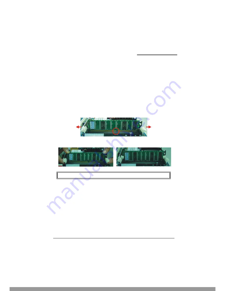
RAM Module Installation:
1. Pull the white plastic tabs on each side of the slot away from the slot.
2. Match the notch on the button of the RAM module with the corresponding pattern in the DIMM
slot. This ensures that the module is inserted properly.
3. Lower the RAM module into the DIMM Slot and press firmly using both thumbs until the
module snaps into place.
4. Repeat steps 1, 2 and 3 for the remaining RAM modules.
Frequency / Voltage Control
This mainboard automatically detects and recognizes the DDR Speed and the CPU Voltage. You can
otherwise override these values using the BIOS Setup Utility.
Configuring using the BIOS Setup Utility
To access the BIOS Setup Utility, reboot your system. During the reboot process you will be given an
opportunity to press the “DEL” key to enter the BIOS Setup Utility.
From the BIOS Setup Utility access the “Advanced” section and then scroll down to the “Frequency /
Voltage Control” field. Adjust the “CPU Host Frequency”, “DDR:CPU Ratio” and “CPU Clock
Ratio” according to the formulas below.
* The pictures above are for reference only and may vary slightly for your mainboard.
This Manual: http://www.manuallib.com/file/2538033


