background image


9

Processor

 - the "central processing unit" (CPU); the principal integrated circuit used 

for doing the "computing" in "personal computer"   

Front Side Bus Frequency - 

the working frequency of the motherboard, which is 

generated by the clock generator for CPU, DRAM and PCI BUS. 

CPU L2 Cache - 

the flash memory inside the CPU, normal it depend on CPU type. 


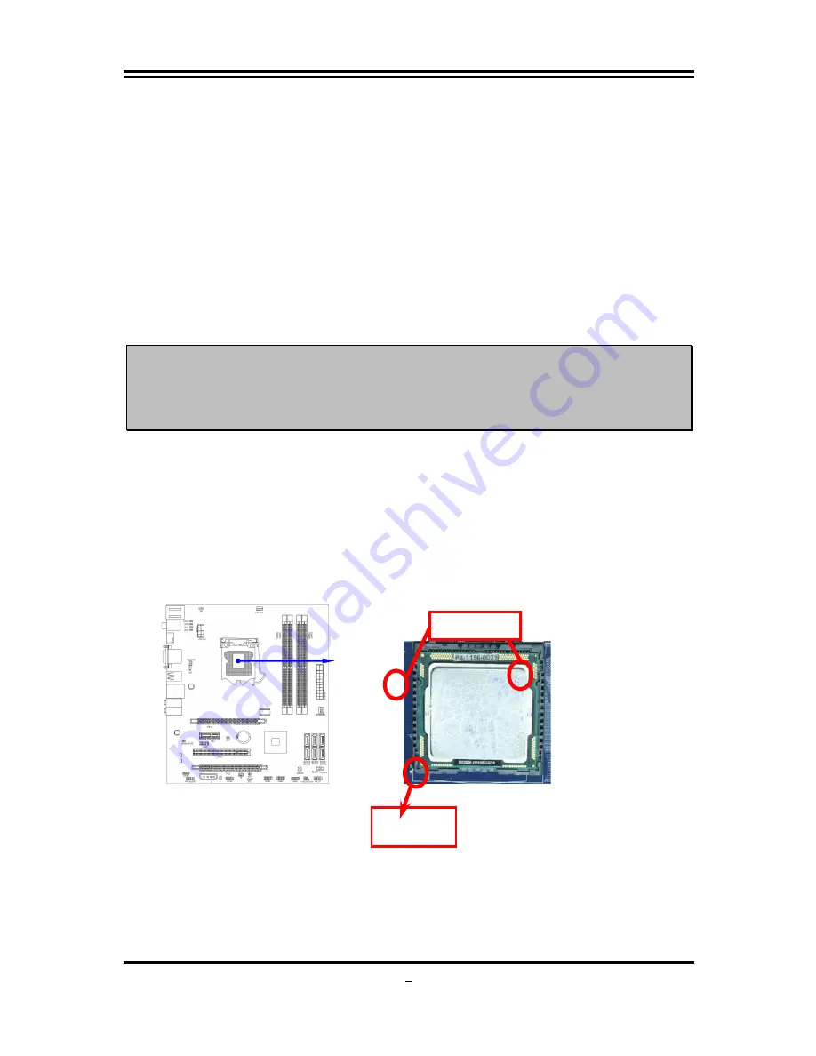
2-3-2 About Intel LGA 1156 CPU Socket 

This motherboard provides an 1156-pin DIP, LGA 1156 Land Grid Array socket, 
referred to as the LGA 1156 socket. 
The CPU that comes with the motherboard should have a cooling FAN attached to 
prevent overheating. If this is not the case, then purchase a correct cooling FAN 
before you turn on your system. 

NOTED! 

Be sure that there is sufficient air circulation across the processor’s 
heat sink and CPU cooling FAN is working correctly, otherwise it 
may cause the processor and motherboard overheat and damage, 
you may install an auxiliary cooling FAN, if necessary. 

To install a CPU, first turn off your system and remove its cover.    Locate the LGA 
1156 socket and open it by first pulling the level sideways away from the socket then 
upward to a 135-degree angle.    Insert the CPU with the correct orientation as shown 
below.    The notched corner should point toward the end of the level.    Because the 
CPU has a corner pin for two of the four corners, the CPU will only fit in the orientation 
as shown. 
When you install the CPU into the LGA 1156 socket, there’s no force required CPU 
insertion; then press the level to locate position slightly without any extra force. 


 Alignment key

 Pin-1 
Indicator

Summary of Contents for H55

Page 1: ...Trademark Specifications and Information contained in this documentation are furnished for information use only and are subject to change at any time without notice and should not be construed as a commitment by manufacturer PMH55 MB Rev 1 0 Manual Rev EG100 Release date January 2010 ...

Page 2: ...i Environmental Protection Announcement Do not dispose this electronic device into the trash while discarding To minimize pollution and ensure environment protection of mother earth please recycle ...

Page 3: ...CONNECTORS HEADERS 15 2 6 1 CONNECTORS 15 2 6 2 HEADERS 18 2 7 STARTING UP YOUR COMPUTER 22 CHAPTER 3 INTRODUCING BIOS 3 1 ENTERING SETUP 23 3 2 GETTING HELP 23 3 3 THE MAIN MENU 24 3 4 STANDARD BIOS FEATURES 25 3 5 ADVANCED BIOS FEATURES 26 3 5 1 CPU FEATURES 27 3 6 ADVANCED CHIPSET FEATURES 28 3 7 INTEGRATED PERIPHERALS 29 3 8 POWER MANAGEMENT SETUP 30 3 9 MISCELLANEOUS CONTROL 31 3 10 PC HEALTH...

Page 4: ... it is moved from a cold environment to a warmer one to avoid condensation phenomenon These water drops attached on PCB or the surface of the components can bring about phenomena as minor as computer instability resulted from corrosion and oxidation from components and PCB or as major as short circuit that can burn the components Suggest starting the computer until the temperature goes up z The in...

Page 5: ...55 chipset based Motherboard 5 User s Manual 5 DVD for motherboard utilities 5 SATA Cable 5 I O Back Panel Shield Intel Core Processor Family Cooling Solutions As processor technology pushes to faster speeds and higher performance thermal management becomes increasingly crucial while building computer systems Maintaining the proper thermal environment is the key to reliable long term system operat...

Page 6: ...ema quality and absolutely software compatibility The H55 Express chipset based motherboard series offer two PCI Express2 0 x16 graphics slots With PE1 being PCI Express 2 0 x16by16 lane slot and PE3 being PCI Express 2 0 x16by4 lane slot These two graphics slots are fully compatible with the latest AMD CrossFireX Technology to guarantee the fully operational Multi GPUs graphics function and avoid...

Page 7: ...ing the working temperature between 20 degrees Centigrade each time intact extension 10 times of effective product operation lives at not rising degrees Centigrade of working temperatures each time a relative one life of product decline 10 only too G P I Function Green power indicator function The full name of G P I technology is Green Power Indicator technology obviously technology utilized to lo...

Page 8: ...ernal Serial ATA ports for six SATA devices providing 3 0 Gb sec data transfer rate Gigabit LAN z Integrated Realtek PCI E Gigabit LAN chip z Supports Fast Ethernet LAN function provide 10Mb 100Mb 1Gb s data transfer rate 8 CH HD Audio z Realtek ALC883 8 channel HD Audio Codec integrated z Support 8 channel 3D surround Positioning Audio z Audio driver and utility included BIOS z AMI 32MB SMT Flash...

Page 9: ...raph HDD 3227 5421 Content Creation Winstone 2004 54 5 Business Winstone 2004 33 5 Winbench 99 V2 0 Business Hi end Disk Winmark99 21600 Business Hi end Graphic Winmark SYSMark 2004 SISMark Rating Internet Content Creation Office Productivity SYSMark 2004 301 3D Creation 2D Creation 570 683 Web publication 474 Communication Document Creation 193 400 DATA Analysis 353 SISOFT Sandra 2005 1 CPU Arith...

Page 10: ...ector PS2 KB MS Port KB1 Coaxial Optical SPDIF_OUT Connectors JBAT Power on Button Serial ATAII Connector SATA 1 2 3 4 5 6 Audio Connector COM Header PCI Express2 0x16by16lane slot Line OUT DVI Connector HDMI Connector PS 2 Mouse Connector KB MS Power On JP1 VGA Connector Over DVI Connector Realtek ALC883 Audio Decode HDMI SPDIF Wi Fi Header 4 pin PWR Connector IR Header JP3 Front Panel Header CDI...

Page 11: ...PEAKER MIC Header 9 pin Block USB2 USB3 USB4 USB Port Headers 9 pin Block SPEAK PC Speaker Header 4 pin Block PWR LED Power LED Header 3 pin Block JW_FP PWR LED Reset HD LED PWR BTN Front Panel Header including Power LED IDE activity LED Reset switch Power On Button lead 9 pin Block CPUFAN1 CPUFAN Header 4 pin Block SYSFAN1 SYSFAN2 System FAN Headers 3 pin Block CDIN CD Audio In Header 4 pin Block...

Page 12: ...Reboot 9 Install Operating System 10 Install Driver and Utility 2 2 Checking Motherboard s Jumper Setting 1 CMOS RAM Clear 2 pin JBAT A battery must be used to retain the motherboard configuration in CMOS RAM short 1 2 pins of JBAT to clear the CMOS data To clear the CMOS follow the procedure below 1 Turn off the system and unplug the AC power 2 Remove ATX power cable from ATX power connector 3 Lo...

Page 13: ...nterface cards and modems runs at 33MHz PCI Express2 0 Peripheral Component Interconnect Express2 0 developed in 2003 the speed of each line doubled from the previous PCI E of 2 5Gbps to 5 Gbps Serial Port a low speed interface typically used for mouse and external modems Parallel Port a low speed interface typically used for printers PS 2 a low speed interface used for mouse and keyboards USB Uni...

Page 14: ...OTED Be sure that there is sufficient air circulation across the processor s heat sink and CPU cooling FAN is working correctly otherwise it may cause the processor and motherboard overheat and damage you may install an auxiliary cooling FAN if necessary To install a CPU first turn off your system and remove its cover Locate the LGA 1156 socket and open it by first pulling the level sideways away ...

Page 15: ...tal protection plate will be pulled up at the same time 4 Remove the plastic protective cap from the socket Put it to the original place if CPU is not installed Do not touch the metal contact point of the CPU socket 5 Make sire that golden finger in the right place as shown in the above illustration and match the two alignment keys on the CPU with two points of the socket CPU can only be correctly...

Page 16: ...counter clockwise direction 3 Press down two fasteners down in the oblique crossing direction as shown above 4 Turn over the motherboard carefully to make sure the fastener insert in the right direction Notice Please apply thermal interface material to the CPU HIS surface The heat sink and installation steps are for reference use only Installation steps might differ depending on different heat sin...

Page 17: ...unction 3 Four DDRIII Memory Modules Plug in DIMM1 DIMM 2 DIMM3 DIMM4 Dual channel Limited 1 Dual channel function only supports when 2 DIMM Modules plug in either both DIMM1 DIMM3 or four DIMM Modules plug in DIMM1 DIMM4 2 Memory modules plugged in the same color DIMM must be of the same type same size and same frequency for dual channel function Install DDR SDRAM modules to your motherboard is n...

Page 18: ...ard on the slot with the screen you remove above 5 Replace the computer system s cover 6 Set up the BIOS if necessary 7 Install the necessary software driver for your expansion card 2 5 2 Assigning IRQs for Expansion Card Some expansion cards need to set up the IRQ to operate An IRQ must be assigned exclusively to single interface use only There are 16 IRQs available but most of them are already b...

Page 19: ... 32 bit PCI slot guarantee the rich connectivity for the I O of peripherals 2 5 4 Installing the CrossFire Bridge Card The following illustrations show you how to install the CrossFire Bridge Card In order to activate the CrossFire technology you have to install the optional Bridge for your CrossFire Tech Supported VGA Cards before you activating the advance multi GPUs functions CrissFire Bridge I...

Page 20: ...mentary switch that connect from the front panel switch to 2 pins Power On jumper pole on the motherboard When the power switch on the back of the ATX power supply turned on the full power will not come into the system board until the front panel switch is momentarily pressed Press this switch again will turn off the power to the system board We recommend that you use an ATX 12V Specification 2 0 ...

Page 21: ... 24 pin power plug 2 ATX 12V Power Connector 8 pin block ATX12V This is a new defined 8 pin connector that usually comes with ATX Power Supply The ATX Power Supply which fully supports LGA 1156 processor must including this connector for support extra 12V voltage to maintain system power consumption Without this connector might cause system unstable because the power supply can not provide suffici...

Page 22: ...rs for Network connection The connector supports 10MB 100MB 1G B s data transfer rate 7 Audio Line In Lin Out MIC RS Out CS Out SS Out connector AUDIO These Connectors are 6 Phone Jack for LINE OUT LINE IN MIC RS Out CS Out SS Out audio connections Line in BLUE Audio input to sound chip Line out GREEN Audio output to speaker MIC PINK Microphone Connector RS OUT BLACK Rear Surround audio output CS ...

Page 23: ...ion SPDIF_OUT1 is a coaxial SPDIF_OUT connector while SPDIF_OUT2 being optical SPDIF_OUT connector 2 6 2 Headers 1 Line Out MIC Header for Front Panel 9 pin FP_AUDIO These headers connect to Front Panel Line out MIC connector with cable Line Out MIC Headers AUDIO Pin 1 Lineout2 L Lineout2 R Sense FB Audio GND LINE2 JD Audio JD 2 9 10 KEY MIC2 L MIC2 JD MIC2 R 2 USB Port Headers 9 pin USB2 USB3 USB...

Page 24: ... rebooting in order to prolong the lift of the system s power supply See the figure below 7 Power switch PWR BTN This 2 pin connector connects to the case mounted power switch to power ON OFF the system System Case Connections HDLED RESET VCC5 GND VCC5 PWR LED PWRBTN PWRBTN PWRLED HDDLE RSTSW NC GND JW FP Pin 1 SPEAK SPKR GND NC VCC5 Pin 1 PWRLED Pin 1 8 FAN Headers SYSFAN1 SYSFAN2 3 pin CPUFAN1 4...

Page 25: ... 1 10 IR infrared module Headers 5 pin IR1 This connector supports the optional wireless transmitting and receiving infrared module You must configure the setting through the BIOS setup to use the IR function IR infrared module Headers IR1 Pin 1 GND 5VX IRRX GN D IRTX 2 5 6 11 Serial COM Port header COM1 COM1 is a 9 pin block header Serial COM Port 9 pin Block Pin1 ...

Page 26: ...n your stereo system has digital input function HDMI_SPDIF Header 1 GND 2 HDMI_SPDIF_OUT 13 WI FI Header WI FI 1 This header supports WI FI Function Connect the wireless local area network adapter to this header It allows you to create a wireless environment and enjoy the convenience of wireless network connectivity WI FI Headers WI FI1 Pin 1 D0 GND USB 5 N C D1 2 11 12 GND USB 5 D1 N C 3 3V D0 ...

Page 27: ...onitor may light up or switch between orange and green after the system is on If it complies with green standards or if it is has a power standby feature The system will then run power on test While the test is running the BIOS will alarm beeps or additional message will appear on the screen If you do not see any thing within 30 seconds from the time you turn on the power The system may have faile...

Page 28: ...own left right to choose in the main menu the option you want to confirm or to modify PGUP Previous Value PGDN Next Value Press F10 when you have completed the setup of BIOS parameters to save these parameters and to exit the BIOS Setup menu Press keys when you want to modify the BIOS parameters for the active option 3 1 Entering Setup Power on the computer and by pressing Del immediately allows y...

Page 29: ...ce Integrated Peripherals Use this menu to specify your settings for integrated peripherals Power Management Setup Use this menu to specify your settings for power management setup Miscellaneous Control Use this menu to specify your settings for Miscellaneous Control PC Health Status Use this item to configure hardware health status User Overclock Settings Use this menu to specify your settings fr...

Page 30: ...s to highlight the item and then use the or and numerical keyboard keys to select the value you want in each item System Date The date format is day month date year Day Day of the week from Sun to Sat determined by BIOS Read only Month The month from Jan through Dec Date The date from 1 to 31 can be keyed by numeric function keys Year The year depends on the year of the BIOS System Time The time f...

Page 31: ...tor of hard disk partition table Quick Boot Allows BIOS to skip certain tests while booting This will decrease the needed to boot the system 1st Boot Device Use this item to specify the boot sequence from the available devices A device enclosed in parenthesis has been disabled in the corresponding type menu Boot Up NumLock Status The default value is On On default Keypad is numeric keys Off Keypad...

Page 32: ...s XP The optional settings are Enabled Disabled Intel R Virtualization Tech When this item is set as Enabled a VMM can utilize the additional HW Caps Provided by Intel R Virtulization Tech Note A full reset is required to change the setting The optional settings are Enabled Disabled Execute Disable Bit Capabili When disabled force the XD feature flag to always return 0 The optional settings are En...

Page 33: ...Chipset Features Setup option is used to change the values of the chipset registers These registers control most of the system options in the computer Configure DRAM Timing by SPD The optional setting is Auto Manual DRAM Command Rate The optional settings are Auto 2T 1T DRAM Margin Ranks The optional settings are Disabled Enabled Memory Hole The optional settings are Disabled 15MB 16MB Initiate Gr...

Page 34: ...e Compatible and Enhanced SATA 2 IDE Configuration The optional settings are Disabled and Enhanced Onboard PCIE Lan Controller Use this item to enable or disable onboard PCIE Lan controller Onboard PCIE Lan BootROM The optional settings are Disabled Enabled USB Functions The optional settings are Disabled Enabled Serial Port1 Address Allow BIOS to Select Serial Port1 Base Addresses ...

Page 35: ... headless operation through ACPI ACPI Aware O S The optional settings are Enabled Disabled Suspend Mode Select the ACPI state used for system suspend The optional settings are S1 POS S3 STR Restore on AC Power Loss The optional settings are power off power on last state Video Power Down Mode Power Down video in suspend or standby mode The optional settings are Disabled Standby and Suspend Suspend ...

Page 36: ...ble inform the PCI device that an ISA graphics devices is installed in the system so the card will function correctly 3 10 PC Health Status This section shows the Status of you CPU Fan and Warning for overall system status This is only available if there is Hardware Monitor onboard CPUTemperature SystemTemperature CPUFAN1Speed SYSFAN1Speed SYSFA N2Speed PCH Voltage 5V SYS 12V SYS VDIMM This will s...

Page 37: ...00ps 1500ps DRAM Clock at Next Boot The optional setting are Auto 800MHz DDR3 800 1066 MHz DDR3 1066 1333MHz DDR3 1333 Host PCI Clock at Next Boot Use the item to set CPU Frequency Range between 133 500 CPU Ratio Use this item to set CPU ratio Use to select value CPU Vcore 7 Shift Use this item to set value in CPU Vcore X Shift function The optional settings are 50mV to 350mV CPU PLL Select Use th...

Page 38: ... eight characters in length and press Enter The password typed now will clear any previously entered password from CMOS memory You will be asked to confirm the password Type the password again and press Enter You may also press Esc to abort the selection and not enter a password To disable a password just press Enter when you are prompted to enter the password A message will confirm that the passw...

Page 39: ... Changes and Exit Save Changes and Exit When you press Enter on this item you get a confirmation dialog box with a message similar to Pressing OK save the values you made previously and exit BIOS setup Discard and Exit When you press Enter on this item you get a confirmation dialog box with a message similar to Pressing OK to leave BIOS setting without saving previously set values Notice The BIOS ...

Page 40: ...INSTALL Menu should appear as below If the menu does not appear double click MY COMPUTER double click CD ROM drive From MENU you may make as selections 1 INF install Intel INF chipset system driver 2 IMSS install Intel IMSS chipset system driver 3 VGA install VGA driver 4 LAN install Gigabit Ethernet NIC Driver 5 SOUND install Audio Codec driver 6 AHCI install Intel AHCI Driver 7 BROWSE CD to brow...

Page 41: ...36 4 1 INF Install Intel INF Chipset System Driver Windows XP Windows XP 64 Windows VISTA VISTA 64 7 x86 7 x64 ...

Page 42: ...37 4 2 IMSS Install Intel IMSS Chipset System Driver Windows XP Windows XP 64 Windows VISTA VISTA 64 7 x86 7 x64 ...

Page 43: ...38 4 3 VGA Install VGA Driver Windows XP Windows XP 64 Windows VISTA VISTA 64 7 x86 7 x64 ...

Page 44: ...39 4 4 LAN Gigabit Ethernet LAN Driver Windows XP Windows XP 64 Windows VISTA VISTA 64 7 x86 7 x64 ...

Page 45: ...40 4 5 SOUND Install Audio Codec Driver Windows XP Windows XP 64 Windows VISTA VISTA 64 7 x86 7 x64 ...

Page 46: ...41 4 6 AHCI Install Intel AHCI Driver Windows XP Windows XP 64 Windows VISTA VISTA 64 7 x86 7 x64 ...

Page 47: ...test BIOS files of the motherboard from official website and then make a copy of it to your bootable floppy disk after decompressing these files STEP 3 Insert the disk into A start your computer and then type in A xxxxxx BAT xxxxxxx being the file name of the latest BIOS STEP 4 Type Enter to update and flash the BIOS The system will restart automatically when BIOS is upgraded ...

Page 48: ... relative power phase working with idle mode Three LED on It means the motherboard is working on partial power saving mode The LED off indicate the relative power phase working with idle mode All LED on It means the motherboard is working at full speed with non power saving mode CPU is working on high load state PWS_LED3 PWS_LED2 PWS_LED1 PWS_LED4 PWS_LED3 PWS_LED2 PWS_LED1 PWS_LED4 PWS_LED3 PWS_L...

Reviews: