Version 2.0
Manual #6410T0021
8
Albany High Speed Doors
Installation & Operation
LEVELING THE DRUM ASSEMBLY
MOUNTING THE DOOR ASSEMBLY (continued…)
11. The photo safety cables are marked and bundled on top of the head assembly at the junction box. Route
the light curtain cables through the holes located at the rear bottom of the mounting brackets as shown.
12. Secure the cables to the sides of the columns using the clips supplied and plug them into the appropriate
photo device mounted in the column—
note the matching cable markings
. Ensure that all loose slack in
the cables is removed. Photo devices are located behind foam insulation on UltraFreeze model doors.
13. UltraFreeze doors will have heat tape in the side columns. Route the power cords for the heat tape up
through the holes located at the rear bottom of the mounting brackets to the junction box on top of the head
assembly.
14. Set the yellow front columns into the side columns. If the door was ordered with light curtains, position the
front light curtain and mounting bracket against the outside of the side columns and secure the light curtain
bracket and the yellow front column with two bolts. Continue installing the remaining bolts provided for each
column.
15. Connect the remaining safety cables to the photo safety devices mounted off the yellow front columns and
hide the cables behind the wire chase covers on the front columns—
note the matching cable markings
.
16. Caulk header and door jambs to seal the opening when finished.
COUNTERWEIGHTS—OPTIONAL EQUIPMENT
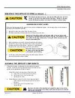
If the door was ordered with counterweights for the optional BacOut egress system, the following steps must be
taken at this point in the installation process:
1. Remove the tie wraps from the counterweight straps and route the straps down to the counterweights.
2. Remove any twists that may be in the straps
3. Loop each strap between the two clamping plates as shown.
4. Pull and hold the straps tight and tighten the clamping bolts.
5. Ensure that all cables/straps are secure and free of any obstructions.
Do not allow the straps to be twisted or slack. Twisted or loose straps
will result in damage to the straps.
The door must be installed to that the roll head assembly is abso-
lutely level, with the side columns plumb and square to the header.
If adjustments are necessary…
1. Loosen the pillow block mounting bolts
2. Lift the low end of the roll with a pry bar until the roll is level
3. Re-tighten the pillow block mounting bolts
4. If necessary, loosen the bolt and adjust the motor torque arm
position to realign the motor so it is parallel with the wall.
Tighten this bolt when done.
Summary of Contents for RapidRoll 355
Page 14: ...13 Manual 6410T0021 1 5 2011 ...
Page 15: ...Version 2 0 Manual 6410T0021 14 Albany High Speed Doors Installation Operation ...
Page 16: ...15 Manual 6410T0021 1 5 2011 ...
Page 17: ...Version 2 0 Manual 6410T0021 16 Albany High Speed Doors Installation Operation ...
Page 18: ...17 Manual 6410T0021 1 5 2011 ...
Page 19: ...Version 2 0 Manual 6410T0021 18 Albany High Speed Doors Installation Operation ...


