background image

Data Logger Manual

Page 13

5.5.iii.b  Device Range (Maximum)


The Maximum Device Range screen can be accessed by pressing the F2 key while viewing the Minimum Device Range 


screen.  This display indicates the maximum values which the OM-CP-PR2000 is capable of detecting and logging.  


Values on this screen cannot be modifi ed.

5.5.iii.c  Calibration Parameters


Pressing F3 while in the Maximum or Minimum Device Range screens will display the device calibration 


parameters. This screen displays information indicating the most recent calibration date as well as the date the 


next calibration will be due. 

It is important to keep your device properly calibrated to ensure accurate readings.


5.5.iii.d  Device Version


Pressing the F4 key while viewing the Maximum or Minimum Device Range screens will display the Device Version  

 screen, 

containing 

information such as fi rmware revision number and communications baud rate.  Values on this 


screen cannot be modifi ed.


5.5.iii.e  Firmware Version


Firmware details can be viewed by pressing the F2 key while viewing the Device Version screens. These details include 

 the 

fi rmware version number, date and time of fi rmware creation, and checksum.

Summary of Contents for OM-CP-PR2000

Page 1: ...User sGuide OM CP PR2000 Pressure Data Logger with LCD Display ...

Page 2: ...tus 8 4 4 Checking power status 8 4 5 Changing the Contrast 9 Section 5 PR2000 Function Reference 10 5 1 Main Screen 10 5 2 Status Menu 10 5 3 Statistics Menu 10 5 4 Units 11 5 5 Setup Menu 11 Section 6 PR2000 Screen Descriptions 14 6 1 Main Screen 14 6 2 Status Screens Run Parameters 14 6 3 Status Screens Memory Status 14 6 4 Status Screens Time 15 6 5 ID Parameters 15 6 6 Statistics Menu Screen ...

Page 3: ... Screens Device Version 21 6 20 Device Information Screens Firmware Version 21 6 21 Calibration Information Screens Calibration Date 21 6 22 Calibration Information Screens Pressure Calibration 22 6 23 Device Reset Screen Hardware Reset 22 6 24 Device Reset Screen Power Interruption 23 Section 7 Computer Interface 24 Section 9 Maintenance 25 Section 10 Warranty Disclaimer 26 Page 2 ...

Page 4: ...n advance programmable stop time Memory 262 143 total readings software configurable memory wrap Reading Rate 1 reading every 2 seconds to 1 every 24 hours Calibration Digital calibration through software Calibration Date Automatically recorded within device Battery Type 6 alkaline AA batteries user replaceable optional AC adapter 7 24 VDC 100mA For 230 VAC operation use AC supply T35 9 100 R 3 ma...

Page 5: ...onment 20 to 60ºC 0 to 95 RH non condensing Dimensions 5 1 x 4 8 x 1 78 130mm x 122mm x 45mm Weight 40 oz 1134 g Enclosure Black anodized aluminum Software Windows 95 98 ME NT 2000 XP based software Dimensions 5 1 x 4 8 x 1 78 130mm x 122mm x 45mm Enclosure Black anodized aluminum Page 4 ...

Page 6: ...a Logger Manual Section 2 Device Overview Page 5 LED Indicators LCD Screen Pressure Sensor Power Jack Communication Jack Up Key Okay Key Down Key Cancel Key Function Keys Black anodized aluminum enclosure ...

Page 7: ...ns indicate the amount of memory left for data storage If the OM CP PR2000 is in wraparound mode the memory status icon will always indicate empty 3 3 Running Indicator Indicates that the OM CP PR2000 is taking readings The icons cycle periodically 3 4 Delay Start Indicator The delay start icon indicates that a logging operation is scheduled for the future 3 5 Wait Icons The wait icon indicates th...

Page 8: ...Data Logger Manual 3 7 External Power Icon Indicates that the OM CP PR2000 is powered by an external source 3 8 Reset Icon Indicates that the device has been reset Page 7 ...

Page 9: ...playing show will appear on the main screen and channels displaying hide will not Button pressing chain Main Screen F4 F1 F1 pressure or F2 pressure graph To change the size of displayed channels From the Main Screen press the F4 key to enter the Setup Menu and from this menu press the F1 key to enter the Display screen then F4 to scroll to the next screen Here the F2 key will change the size of t...

Page 10: ...CD screen contrast values can be changed in two ways One method is outlined in the Function Reference Guide A faster simpler way involves simultaneously pressing the CANCEL and UP or DOWN button repeatedly in any screen Button pressing chain CANCEL UP repeatedly to increase or DOWN repeatedly to decrease Page 9 ...

Page 11: ...n record max readings as well as information about the wrap feature displaying either disabled or the number of wrap readings currently stored in memory 5 2 iii Time and Date The time and date screen displays current time data including the current time and date time and date of last measured data and current time zone 5 3 Statistics Menu Pressing the F2 key while in the Main Screen brings up the ...

Page 12: ...creen Here the F1 and F2 key correspond to the pressure channel and pressure graph respectively Pressing these function keys results in highlighting their corresponding channel function tab While a channel is highlighted the corresponding display function can be toggled between Hide and Show with Hide indicating that the channel will not be displayed on the main screen and Show indicating that it ...

Page 13: ...wer Modes screen brings up the Display Update Mode screen On this screen options relating to the refresh rate of the screen are displayed The F1 key changes the refresh rate of the whole main screen and the F2 key changes the refresh rate of the graphing feature Both parameters toggle between auto and reading In auto mode the display is updated periodically according to the time displayed by the A...

Page 14: ...s information indicating the most recent calibration date as well as the date the next calibration will be due It is important to keep your device properly calibrated to ensure accurate readings 5 5 iii d Device Version Pressing the F4 key while viewing the Maximum or Minimum Device Range screens will display the Device Version screen containing information such as firmware revision number and com...

Page 15: ...meters including date of recording start start date time of recording start start time stop date stop time recording rate and current status For all status screens F1 RUN displays run parameters screen F2 MEM displays memory status screen F3 TIME displays date and time screen F4 MORE displays ID parameters screen CANCEL returns to main screen OK returns to main screen UP no function DOWN no functi...

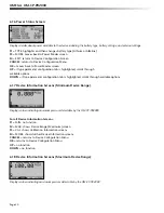
Page 16: ...d date and time zone information For all status screens F1 RUN displays run parameters screen F2 MEM displays memory status screen F3 TIME displays date and time screen F4 MORE displays ID parameters status screen CANCEL returns to main screen OK returns to main screen UP no function DOWN no function 6 5 ID Parameters Displays information relating to device identity For all status screens F1 ID no...

Page 17: ...verage recorded value for the pressure channel F1 PRESS Displays pressure statistics F2 no function F3 no function F4 EXIT returns to Statistics Menu Screen CANCEL returns to Statistics Menu OK returns to Statistics Menu UP no function DOWN no function 6 8 Type Statistics Displays statistics from from the pressure channel sorted by type maximum recorded value minimum recorded value or average valu...

Page 18: ...to Statistics Menu OK returns to Statistics Menu UP no function DOWN no function 6 10 Unit Selection Menu Displays units currently being used for each channel F1 PRESS selects pressure channel for unit change F2 GRAPH selects graph feature for unit change F3 no function F4 OK returns to Main Screen Note Unit selection can be changed by pressing the corresponding function key repeatedly or using th...

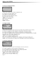
Page 19: ...CE first highlights and then changes the option for how often the graphing feature will update F4 MORE moves on to Display Configuration screen CANCEL return to Display Configuration Menu OK moves on to Display Configuration screen UP once channel parameter configuration tab is highlighted scrolls through available options DOWN once channel parameter configuration tab is highlighted scrolls throug...

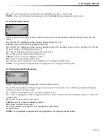
Page 20: ...Device Configuration Menu OK moves to Display Update Mode screen UP once parameter configuration tab is highlighted scrolls through available options DOWN once parameter configuration tab is highlighted scrolls through available options 6 15 Display Update Mode Screen Displays information regarding display refresh mode and refresh interval F1 MODE first highlights and then changes the screen updat...

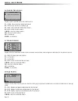
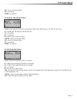
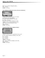
Page 21: ...ilable options DOWN if type parameter configuration tab is highlighted scrolls through available options 6 17 Device Information Screens Minimum Device Range Displays values indicating minimum pressure detectable by the OM CP PR2000 For all Device Information Screens F1 MIN no function F2 MAX shows Device Range Maximum screen F3 CAL shows Calibration Information screens F4 MORE shows further Devic...

Page 22: ...ce firmware version information F1 VERS shows Device Version screen F2 FIRM no function F3 MORE shows Device Range Minimum screen F4 EXIT returns to Device Configuration Menu CANCEL returns to Device Configuration Menu OK returns to Device Configuration Menu UP no function DOWN no function 6 21 Calibration Information Screens Calibration Date Displays date of last calibration and due date of next ...

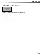
Page 23: ...RESS no fucntion F4 EXIT returns to Device Information screens CANCEL returns to Device Information screens OK returns to Device Information screens UP no function DOWN no function 6 23 Device Reset Screen Hardware Reset Displayed as notification when a hardware reset has occurred F1 OK accepts notification and displays main screen F2 no function F3 no function F4 no function CANCEL no function OK...

Page 24: ...d as notification when power is interrupted during device operation F1 OK accepts notification and displays main screen F2 no function F3 no function F4 no function CANCEL no function OK accepts notification and displays main screen UP no function DOWN no function Page 23 ...

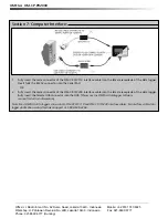
Page 25: ...ata logger Fully insert the female USB connector into the USB Please see the OMEGA Datalogger Software manual for further information Note Most OMEGA data loggers can use both OM CP IFC110 and OM CP IFC200 interface cables For interface cable data logger clarification contact technical support at 1 800 848 4286 Office Jl Radin Inten II No 62 Duren Sawit Jakarta 13440 Indonesia Workshop Jl Pahlawan...

Reviews: