

3
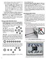
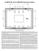
the unit to a wall or other flat surface using the hardware
provided (see page 4 for printed template).
As shown in Fig. 2, the rear housing includes two mount-
ing holes for single-gang (
A
) and four mounting holes for
double-gang (
B
) electrical utility boxes, as well as four all-
purpose holes (
C
) for mounting to drywall or other surfac-
es (use minimum #6 screws suitable for the surface).
"
EXPANDER GROUP" DIALS
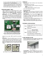
Inside the Expander are 2 rotary dials (see Fig. 3). These
dials are used to set the "Expander Group". All version 2
Gateways include an identical set of dials.
Therefore, the
dial values set on your Gateway MUST then match the dial
values set on your AL-IME2-EXP
Expanders.
IMPORTANT: Each Gateway in your system MUST be
set to a different "Expander Group" value along with its asso-
ciated Expanders. The "Expander Group" dial setting deter-
mines which Expanders are associated with which Gateway,
thus preventing Gateways from discovering unintended Ex-
panders.
Expander Group values of "
00
" through "
99
" are valid selec-
tions.
IMPORTANT:
The small "selection arrow" on each dial
must be pointing directly to the desired Group value. In Fig.
4 (below), the Group value is set to "
50
". Use a small flat-
head screwdriver to turn the dials and make the selections.
Be sure to orient the Expander as shown above with the RE-
SET button ABOVE the dials to ensure proper Group
setting!
POWER UP
Connect the 6VAC power transformer wires (non-polarized).
Upon power up:
●
Red LED solid (momentarily)
●
Yellow LED blinks (counting out "Expander Group" dial
setting).
Note:
Zero = No blink
●
Yellow LED solid + green LED flickering rapidly
Next, reset the Expander as follows:
Reset the Expander
IMPORTANT:
Before securing the Expander housing
cover,
ALWAYS
reset the Expander memory, even if the
Expander is new "out of the box" and/or has never been
used previously.
After initial power up, press and hold the "RESET" button
(see below for location); continue to hold the button until the
red light turns on solid. Now, release the button and the
green light will flicker rapidly
.
This "resetting" of the Expander clears all memory and en-
sures that any previous data is cleared from the unit.
Note:
Resetting the Expander also re-writes the
"Expander Group" dial setting into the Expander memory.
EXPANDER LED INDICATIONS
CLOSE HOUSING COVER
Close the housing cover by first engaging the hooks at the
top, then snapping the bottom together. Secure the cover
with the Bottom Screw provided as shown in Fig. 5.
Congratulations! You're finished!
Now go to the DL-
WINDOWS™ for Networx™ V5 USER'S GUIDE (OI383) for
instructions about discovering your Expanders from DL-
Windows.
Fig. 5: Bottom Screw
Fig. 3: "RESET" button and two "Expander Group dials"
Be sure to orient the Expander with the RESET button ABOVE
the dials as shown above to ensure proper Group setting !
RESET
button
Expander
Group
Dials
Yellow
On Power up, displays "Expander Group" dial setting (in
two sequences)
Receiver On (normal operation)
Red
Transmitter on
(Expander Status)
Not configured - Rapid blinking / flickering
Idle / configured - 1 blink per second
Lock Communication Fail - 2 blinks (continuously)
Expander Communication Fail - 4 blinks (continuously)
Green
Fig. 4. Example: The above Expander Group dials are set to "50"
"selection
arrow"
"selection
arrow"


