


3
CONNECTING TO A NETWORK
The
AL-IM2-80211
Gateway can be used wired or
wirelessly. However, "out of the box", the Gateway is
configured for a wired connection only. (See section
Wireless (80211) Configuration
below for configur-
ing wireless connectivity). Connect RJ-45 cable to the
network, and apply power via the class 2 VAC trans-
former. Upon connection, the Gateway automatically
begins searching for a valid IP address from the net-
work (see the
POWER UP
section on page 4).
IMPORTANT:
Gateways can ONLY be discovered
by DL-Windows when the PC running DL-Windows is
on the same subnet as the Gateway. Refer to
Subnet
section for more information.
Static IP Addresses
We recommend using static IP addresses for each
Gateway:
●
DL-Windows software performs faster; no wasted
time re-locating Gateways that have had their IP
addresses changed by DHCP
●
Static IP addresses allow operation across subnets
in large corporate networks (such as those that ex-
ist between buildings)
●
Static IP addresses allow Emergency Commands
(such as "Emergency Lockdown") to perform
properly
Contact the Network Administrator
If you know the Gateway will be installed on a large
corporate network that includes multiple subnets, we
recommend you start by contacting the corporate net-
work administrator and request the following:
●
IP Address - An address for each Alarm Lock Gate-
way device
●
Subnet Mask - Filtering data ("mask bits") as re-
quired by the aforementioned IP address
●
Default Gateway - The address of the physical de-
vice, such as a router, for the current subnet to
which DL-Windows will be connected
●
Wireless Network Configuration - The wireless net-
work security settings, authentication, encryption,
etc.
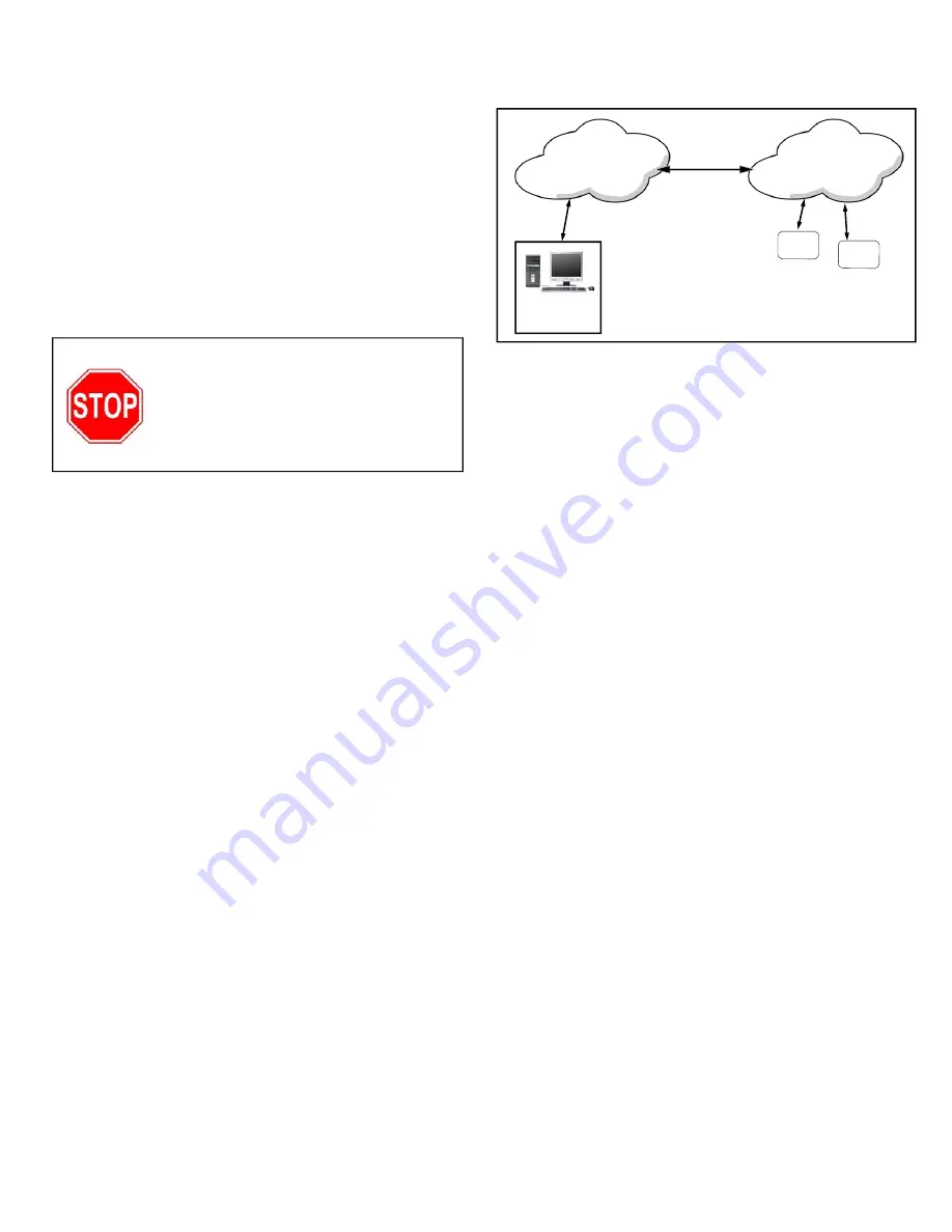
Subnets
To improve security and processing performance, cor-
porate networks are often divided into interconnected
but separate "subnet" segments. The network admin-
istrator may decide to use routing tables or may speci-
fy blocks of addresses through which the two subnets
can freely communicate in both directions. However, if
the two subnets cannot freely communicate as in the
illustration below, in order to communicate to the Gate-
way across the subnet, follow the steps below:
●
Connect the Gateway to local network (DL-
Windows on same subnet); Gateway receives val-
id IP address
●
Using DL-Windows, Discover and add the Gate-
way to an Account
●
Configure Gateway with the static IP address infor-
mation of the subnet you plan to communicate with
●
Disconnect from the local network - remove power
from the Gateway (Gateway will retain static IP
information)
●
Re-connect / re-apply power in the desired loca-
tion / subnet
Wireless (80211) Configuration
DL-Windows cannot Discover a Gateway wirelessly; it
must first be Discovered via a wired connection, then,
you can configure the Gateway to be wireless. Similar
to the steps above (in the
Subnet
section) follow the
steps below:
●
Connect the Gateway to local network (DL-
Windows on same network as wireless router or
wireless access point); Gateway receives valid IP
address
●
Using DL-Windows, Discover and add the Gate-
way to an Account
●
Configure Gateway with the proper wireless net-
work security settings, authentication and encryp-
tion
●
Disconnect from the local network - Gateway will
retain wireless information
●
If Gateway is moved to a new location, simply re-
apply power; the Gateway will now communicate
wirelessly to your network!
The following sub-sections refer to
the DL-Windows software, therefore
the following terminology may be
better understood by referencing
OI383 (included with your Gateway).
Subnet
173.16.100.xxx
Subnet
173.16.200.xxx
Fig. 3: Gateways on different subnets within a network
PC Running
DL-Windows
Software
ROUTER or
SWITCH or SERVER
GATEWAY
GATEWAY


