Alan HM135 Service Manual Download Page 5

HM135 

Service Manual 

Preliminary version 

Page 5 of 13


2.3  Front panel (head) circuitry 

The microprocessor 

DD800 

runs off a 8 MHz oscillator which is composed of 

X800

, and 

R829

DD800

 is basically 

used to control the LCD unit 

XT80

, to decode the commands coming from the front keypad 

S801

 to 

S808

) as well 

as to switch the front LEDs 

DA800

. It is also used to light up the LCD backlight (

VD800

 to 

VD805

) as well as for 

the PTT circuit as over stated.  

The negative voltage necessary for the LCD is created by a charge pump which consists of 

VT815

VT813

VT812

VD809

 and 

VD808

. The output (line 

–8V

) is fed to the regulator 

DA804:A

 which outputs the line 

VD

 in 

order to supply the LCD unit. 

The hang-up functions work this way: the line 

AUX_HOOK

 is connected to the microphone’s hook and it’s 

normally grounded (microphone hooked). When the mike is removed from its hook,  the line 

AUX_HOOK

 changes 

its state driving the transistor 

VT809

. This changes the status of the pin 

21

 of the microprocessor 

DD800

 which 

opens the monitor through a command sent to the main microprocessor 

DD5

 through a serial command. 

2.4  VCO / Synthesizer (PLL) 

This section basically consists of the Temperature-Compensated Crystal Oscillator (TCXO), Voltage Controlled 
Oscillators (VCOs), Synthesizer and the Loop Filter.  

2.4.a 

Temperature-Compensated Crystal Oscillator (TCXO)


The reference oscillator is composed by the temperature compensated crystal X2 and related circuitry (DA1:A. 

VD19

VD20

VT21

 and 

VT20

), 

RP2

 is used to adjust the oscillator on frequency (12.8 MHz) at room temperature. 

The reference oscillator is held within the specifications 

±

5 ppm from -25 to +55

2.4.b Voltage-Controlled 

Oscillators 

The receive VCO consists of 

VT11

CV1

VD6

 and 

VD9

. This VCO oscillates at 45.1 MHz above the programmed 

receive frequency (i.e. from 181.1 to 219.1 MHz for the 135-174 MHz range). The VCO’s oscillating frequency is 
tuned by the varactors 

VD6 

and 

VD9

.  

The transmitter VCO consists of 

VT17

CV2

VD11

-

VD12

 and 

VD13

-

VD14

 and oscillates directly to the TX carrier 

frequency range (i.e. from 135 to 174 MHz range). The TX VCO is directly frequency-modulated by means of the 
varactor 

VD15

 which is driven by the modulating signal (line 

A

) regulated by the trimmer 

RP4

. This is part of the 

double-point modulation and works mainly in high AF modulating frequencies), the other part of the double point- 
modulation is explained in the par. “Transmitter Audio Circuits”. 

The tuning voltage for the VCOs is supplied from the output of the Loop Filter made with 

R73

R74

R78

C99

C100

 and 

C101

Only one of the VCOs runs at a time. In RX the line 

RXC

 (which is obtained from the 

+8V_RX

 line coming from 

the voltage switch 

VT41

) is high enabling the RX VCO via the transistor 

VT16

. During this time the line 

TXC 

(which is obtained from the 

+8VTX

 line coming from the voltage switch 

VT42

) is low, so the TX VCO is disabled. 

When the PTT is pressed, the 

RXC

 line becomes low switching the RX VCO off. At the same time the line 

TXC


goes high activating the TX VCO via the transistor 

VT18

.  

The output of the VCOs are AC coupled (

C91

 and 

C109

) and sent to the synthesizer buffer 

VT19

, then sent to 

DA5

 for an additional buffering. The output of 

DA5

 is connected to the low-pass filter (

L27

L28

L29

 and related 

capacitors), then directly sent to the TX stages (line 

HET_TX 

which


is sent to the pre-driver amplifier 

VT24

) or RX 

stages (line 

HET_RX 

which is sent to


the RX mixer 

A1

) due to the RF switching action provided by 

VD16

 and 

VD17

 which are controlled by the lines 

+8VRX

 and 

8V_TX_F

 respectively (this last line is obtained from the line 

+8VTX passed through the filter created with 

L52

L53

 and related capacitors). The output from the VCO 

necessary to feedback the PLL IC 

DA3

 (i.e. line 

PLL_RF

 send to pin 

8

) is directly output from 

VT19

 and fed 

through 

R106

C362

 and 

C134

. , whilst the other part of the signal is fed to 

DA5

, then passed through the low-

pass filter (

L27

L28

L29

C130

C132

C133

 and 

C131

). Diodes 

VD16

 and 

VD17

 act as signal switches in order 

to feed the signal to RX or TX stages at the appropriate time according to the switching voltages which are, 
respectively, the lines 

+8VRX

 and 

8V_TX_F

The PLL IC 

DA3

 receives the reference signal from the TCXO (pin 

1

) and the feedback from the VCO (pin 

8

). The 

synthesizer is tuned in 5.00 KHz or 6.25 KHz steps. The output from the PLL IC (pin 

15

 and 

16

) is used to drive 

the PLL charge pump which consists of 

VT12

VT13

VT14

 and 

VT15

, then the charge pumps sent the output to 

the PLL filter in order to close the loop. 

Summary of Contents for HM135

Page 1: ...HM135 Service Manual Preliminary version Page 1 of 13 ALAN HM135 Mobile VHF Transceiver Service Manual Copyright 2004 by CTE International Italy all rights reserved...

Page 2: ...Front End 7 2 6 b Local Oscillator LO 7 2 6 c Mixer 8 2 6 d FM Detector and Squelch 8 2 6 e Audio routing 8 2 6 f CTCSS DCS signal routing 8 2 6 g Selcall signal routing 8 2 7 Signaling 8 2 7 a Gener...

Page 3: ...epending on the version from 9 KHz to 1 GHz 36 dBm Spurious Emissions W from 1 to 4 GHz 30 dBm Modulation System FM F3E PM G3E Maximum Deviation KHz 2 5 12 5 KHz 5 25 KHz Adjacent Channel Power Attenu...

Page 4: ...TCSS DCS signal line MCU_CTCSS_DCS_PWM as further explained The digital signals coming from the ADC converters which drive the microprocessor in order to decode the Selcall and CXTCSS DCS signals are...

Page 5: ...is driven by the modulating signal line A regulated by the trimmer RP4 This is part of the double point modulation and works mainly in high AF modulating frequencies the other part of the double poin...

Page 6: ...eds the driver amplifier VT23 whose output from the driver stage feeds the final RF power amplifier VT22 to produce the rated output power of 25 watts The output of the power amplifier is applied to t...

Page 7: ...with the speech Selcall signal DA9 C sums the two signals speech Selcall coming from pin 11 of DA10 and CTCSS DCS coming from pin 12 feeding its combined output to DA9 D which is a 3 KHz low pass fil...

Page 8: ...switch VT54 controlled by the transistor VT55 2 6 e Audio routing The detector s audio output line DETECTOR_AUDIO is fed to DA13 A and DA13 B 3 KHz low pass filter deeply described in the next paragra...

Page 9: ...ector as explained in par Selcall signal routing 2 8 ON OFF switch rear connector and internal connectors 2 8 a ON OFF switch The line ON OFF_SWITCH is normally pulled up by the resistor R182 When the...

Page 10: ...f RP6 and Ground Turn RP6 in CCW direction until readings of the ohmmeter are within 100 to 300 Ohm 4 Connect an ohmmeter between the wiper of RP7 and Ground Turn RP7 in CCW direction until readings o...

Page 11: ...n LCD It is OK Switch OFF the Radio 3 5 Programming the radio 1 Connect the programming cable to radio s Microphone Connector 2 Press the F1 key keep it pressed and switch ON the radio Radio will resp...

Page 12: ...een 9 and 10 W 3 9 Setting of modulation 1 VERY IMPORTANT Switch off all the modulator filters in the deviation meter communication tester before this measurement Radio s modulation input used for thi...

Page 13: ...radio s antenna connector 4 Set the RF generator modulation frequency to 1kHz and the deviation to 3 KHz Set the RF output of the generator to 87 dBm 10 uV 5 Decrease the level of RF generator until...

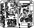
Page 14: ...ALAN HM 135 TEST POINTS AND PCB LAYOUTS...

Page 15: ...p d f M a c h i n e b y B r o a d G u n S o f t w a r e TP1 Freq Adj Ref Mod Adj VCO Mod Adj TX VCO Adj RX VCO Adj Driver Bias TX PA Bias TX Pwr Cal Squelch level TEST POINTS...

Page 16: ...p d f M a c h i n e b y B r o a d G u n S o f t w a r e...

Page 17: ...p d f M a c h i n e b y B r o a d G u n S o f t w a r e...

Page 18: ...p d f M a c h i n e b y B r o a d G u n S o f t w a r e...

Page 19: ...p d f M a c h i n e b y B r o a d G u n S o f t w a r e...

Page 20: ...p d f M a c h i n e b y B r o a d G u n S o f t w a r e...

Page 21: ...p d f M a c h i n e b y B r o a d G u n S o f t w a r e...

Page 22: ...p d f M a c h i n e b y B r o a d G u n S o f t w a r e...

Page 23: ...p d f M a c h i n e b y B r o a d G u n S o f t w a r e...

Page 24: ...p d f M a c h i n e b y B r o a d G u n S o f t w a r e...

Page 25: ...p d f M a c h i n e b y B r o a d G u n S o f t w a r e...

Page 26: ...ALAN HM 135 ELECTRICAL DIAGRAMS...

Page 27: ...HM135_HEAD_FEB_14_2004 SCH p d f M a c h i n e b y B r o a d G u n S o f t w a r e...

Page 28: ...12 13 14 D 5 6 7 B 10 8 9 C p d f M a c h i n e b y B r o a d G u n S o f t w a r e...

Page 29: ...5 6 7 B 12 13 14 D 1 2 3 A 1 2 3 A 10 8 9 C p d f M a c h i n e b y B r o a d G u n S o f t w a r e...

Page 30: ...1 2 3 4 8 A 1 2 3 4 8 A 5 6 7 B 10 8 9 C 5 6 7 B 1 2 3 4 8 A 5 6 7 B 1 2 3 A 12 13 14 D 1 2 3 4 8 A p d f M a c h i n e b y B r o a d G u n S o f t w a r e...

Page 31: ...10 8 9 C 5 6 7 B 1 2 3 A 5 6 7 B 12 13 14 D p d f M a c h i n e b y B r o a d G u n S o f t w a r e...

Page 32: ...p d f M a c h i n e b y B r o a d G u n S o f t w a r e...

Page 33: ...1 2 3 4 8 A p d f M a c h i n e b y B r o a d G u n S o f t w a r e...

Page 34: ...5 6 7 B p d f M a c h i n e b y B r o a d G u n S o f t w a r e...

Page 35: ...5 6 7 B 10 8 9 C 1 2 3 A 12 13 14 D p d f M a c h i n e b y B r o a d G u n S o f t w a r e...

Page 36: ...p d f M a c h i n e b y B r o a d G u n S o f t w a r e...

Page 37: ...ALAN HM 135 EXPLODED VIEW AND PART LIST...

Page 38: ...ALAN HM 135 PROGRAMMING MANUAL...

Page 39: ...HM135 HM435 Programmer software guide Preliminary version Page 1 HM135 HM435 VHF UHF Mobile Transceiver Programmer Software Guide Preliminary version issued on February 15th 2004...

Page 40: ...ht 2004 by CTE International Italy all rights reserved Microsoft MS and Windows are registered trademarks of Microsoft Corporation IBM is a registered trademark of International Business Machines Corp...

Page 41: ...TX calls Call1 Call2 Emergency Transpond and Auto ID ANI 16 5 5 Monitor Key Behaviour 16 5 6 Manual Autoreset for selective calls 18 5 7 Overviewing a Channel Data Summary 18 6 CUSTOMIZATIONS 20 6 1...

Page 42: ...onal radio systems radio system and radio network settings parameters as well as general PC operation This programming guide is subject to change without notification This booklet is referred to the c...

Page 43: ...exe file 5 Click OK and then follow the instructions which appear 6 Several windows will ask you to insert your user s information choose a destination location for the program and finally select the...

Page 44: ...ou need to remove the RJ connector from the transceiver s microphone socket unlock it by pushing the side release button of the RJ connector and remove it by grasping the connector itself not the cabl...

Page 45: ...ed as default 3 3 Checking the software version If you want to see the software version and other additional info from the menu Help select About The About window will open showing you the said data 3...

Page 46: ...you want to create any name will do anyway we recommend to type the customer s name then press the Save button the Channel Data window will open Important we ll always refer this window as Channel Dat...

Page 47: ...sensitivity area and select either the Local or Distance radio button for that channel depending on your needs For regular applications we recommend to use the maximum sensitivity by keeping the defau...

Page 48: ...l 1 in the figure will open 3 If you need to activate the CTCSS encoder click on the TX tone Hz drag down button and select the tone encoding frequency you need e g 110 9 Hz 4 If you need to activate...

Page 49: ...1 Switching between Channel Data and Global Data windows Starting from now we ll need to switch between Channel Data and Global data Windows Global data window can be recalled at any time by clicking...

Page 50: ...Up 2 area is useful to set up the emergency call For further information please see the paragraphs 6 8 The Tables area allows you to define the parameters for the Selective Calls ref par 6 1 setup RX...

Page 51: ...the following example we selected the sequence 1 4 If you want to assign an alphanumeric name to the selected Rx sequence just type the new name over the existing one RxSeq x in the example we rename...

Page 52: ...ttings in case of big mistakes In this case click the button located in the uppermost right corner and start from the beginning of this paragraph If you composed a completely wrong sequence set up you...

Page 53: ...ght to the next paragraph Close the Tx sequence set up without entering all the settings in case of big mistakes In this case click the button located in the uppermost right corner and start from the...

Page 54: ...y Just go to the Wait before transpond on BUSY Channel drag down button and select the time you need which is available in 2 5 sec steps 7 Select the condition in which you want the transceiver be sen...

Page 55: ...software guide Preliminary version Page 17 1 Be sure you are selecting parameters on the right channel if not please select the right one by clicking on either the or button in the Channel num area i...

Page 56: ...ed by default checkbox click the Autoreset button the Autoreset window will open 4 Select the autoreset time you need by clicking the Autoreset drag down button and then click the needed time You can...

Page 57: ...will remain on the screen providing an useful programming monitor In fact it can be manually updated every time you press the Update button or automatically after any programming operation you will m...

Page 58: ...s of the standard Selcals Moreover if you don t want to use the standard Selcal tone frequencies you can totally define your own Selcal standard called PERSONAL 1 From the Global Data window Tables ar...

Page 59: ...Global Data window Set Up area click the Scan configuration button the Scan configuration window will open 2 In the Scanning conditions area you can define the condition in which the scan should stop...

Page 60: ...nel accessed if you want to automatically select the last channel used before it was switched off Click the Txed selcal drag down button and select the required selcal to automatically being sent ever...

Page 61: ...ic signals as follows From the Global Data window Set Up area click the Key Warn beeps button you will toggle it OFF or ON depending on the times you press the button We recommend when possible to lea...

Page 62: ...Number of burst 1 255 box then type the number of trills alternations of Tone 1 and Tone 2 per burst in the Number of trill per burst box 7 If you have selected more than one burst for each ring you c...

Page 63: ...set LCD contrast and backlight and the default squelch level Moreover you can enable disable a variety of miscellaneous settings such as the microphone with keypad the optional internal scrambler boar...

Page 64: ...lso decide to assign selcalls to one or more F key s 1 From the Global Data window Tables area click the Menu manager button the Menu manager window will open 2 To enable a menu or submenu go to the S...

Page 65: ...message after clicking on Program data button WHICH RADIO Radio type HM35 START_UPLOAD UPLOAD_SYS_RADIO_DATA UPLOAD_RX_SEQ_DEF x These two messages are repeated for each RX channel x is the number of...

Page 66: ...t be blank gray otherwise close the file with the command File Close radio 2 From the menu Options select Restore System DB A window will open with the message Restore the SYSTEM DB Default Public Dat...

Page 67: ...required programming data or browse it using the directory tree in folder box programming files use the extension hmv or hmu and are usually placed in the directory C Programs HM135 Programmer usrDB...

Page 68: ...your computer 5 Package contents 5 System requirements 5 M Manual Autoreset for selective calls 18 Menu F keys customization 26 Monitor Key Behaviour 16 N New or already stored data 7 P Programming mo...

Page 69: ...ing timing speed priority wait 21 scanning with CTCSS DCS 21 scanning with Selcal 21 special BUSY Tx lockout 23 Squelch level 25 Tx PTT resume timer 23 Tx timeout timer 23 Software installation 5 T Ta...

Reviews: