18
2 Wiring
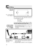
2.1 Circuit
Diagram
Fig. 1: Microphone
circuit diagram.
2.2 Connecting
the Microphone
to a Balanced
Input
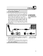
Fig. 2: Using a
balanced connect -
ing cable.
The microphone provides a balanced output on a
3-pin male XLR connector:
Pin 1: ground
Pin 2: hot
Pin 3: return
You can connect the microphone either to a balan-
ced or an unbalanced microphone input.
1. Use a commercial XLR cable such as the op-
tional MK 9/10 from AKG.
The length of these cables does not affect au-
dio quality.
2. Plug the female XLR connector on the micro-
phone cable into the male XLR connector on
the microphone.
3. Plug the other connector on the microphone


