30
29
ALIGNMENT SET-UP PROCEDURES
TUNER SECTION
CASSETTE SECTION
IC101
TC102
test point
test point
17
T102 TC101
1
2
2
4
5
3
L106
C123
( )
L102
L101
T103
1
5
3
CD6606-01-01
test point
T201
C216
3
2
2
1
1
SFR251
SFR201
1. AM IF Adjustment
4. FM Frequency Range Adjustment
Test point: IC101 (TA2149BN) 17 PIN
Test point: C123
Adjustment location: T103
Adjustment location: L101
T103 ------------------- 450kHz
Set tuner frequency to be 87.5MHz.
Adjust L101 so that voltage of test point is 2.5±0.05V.
2. AM Frequency Range Adjustment
Change tuner frequency to be 108MHz, the voltage
Test point: C123
of test point should be less than 9.5V.
Adjustment location: T102
Set tuner frequency to be 522kHz.
5. FM Tracking Adjustment
Adjust T102 so that voltage of test point
Test point: IC101 (TA2149BN) 17 PIN
is 1.7±0.05V.
Adjustment location: L102, TC102
Change tuner frequency to be 1620kHz,
L102 ------------------- 90MHz waveform max.
the voltage of test point should be less
TC102 ----------------- 106MHz waveform max.
than 9.5V.
3. AM Tracking Adjusment
Test point: IC101 (TA2149BN) 17 PIN
Adjustment location: L106, TC101
L106 ------------------- 603kHz waveform max.
TC101 ----------------- 1404kHz waveform max.
CD6606-01-02
1. Bias Frequency Adjustment
Test point: C216
Adjustment location: T201
T201 ------------------- 60kHz±1kHz
2. Bias Level Adjustment
Test point: C216
Adjustment location: SFR201
SFR201 --------------- 13V±1V
3. Tape Speed Adjustment
Test point: headphone jack
Adjustment locaiton: SFR251
SFR251 --------------- 3000Hz±90Hz
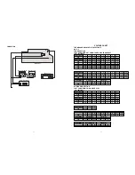
EQUIPMENT CONNECTION DIAGRAMS
DIGITAL MULTMETER
2CH AC VOLTMETER
OSCILLOSCOPE
OUT
IC101
17
8
C123
( )
FREQUENCY COUNTER
2CH AC VOLTMETER
C216
AM SECTION
CD6606-01-01
CASSETTE SECTION
CD6606-01-02


