background image

3


v

li

b

re

v

b

v

p

h

v

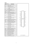
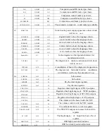
Pin14: +8V power source supply. 

Pin15: Using a capacitor of 220n in series to GND, This pin decouples the internal digital supply 

oltage of the video processor and minimizes the disturbance to the sensitive analogue parts. 

Pin16: PHI-2 control loop, this pin requires a capacitor at 2.2nF (C) in series to GND. 

Pin17: PHI-1 control loop, the loop filter connected to pin 17 is suitable for various signal conditions 

ke strong/weak and VCR signal. This is achieved by switching of the loop filter time constant 

y changing the PHI-1 output current. 

Pin18: GND. 

Pin19: Bandgap decoupling, the bandgap circuit provides a very stable and temperature independent 

ference voltage. This reference voltage (4.0 V) ensures optimal performance of the analogue 

ideo processor part of the N301 and is used in almost all functional circuit blocks. 

Pin20: East-west pillow signal output. 

Pin21: Pin22

Vertical drive output. 

Pin23: Pin24

IF input


Pin25: Reference current, This pin requires a resistor to ground. The optimal reference current is 

100mA which is determined by this resistor. The 100mA reference current should not be changed   

ecause the geometry processor is optimised for this current. Furthermore the output current of 

ertical drive and EW are proportional to this current. 

Pin26: Vertical sawtooth, This pin requires a capacitor to ground of 100nF 

Pin27: AGC output. This output is used to control (reduce) the tuner gain for strong RF signals. 

Pin28: Audio de-emphasis. 

Pin29: Sound decoupling. This pin requires a capacitor connected to ground. The pin acts as a low 

ass filter needed for the DC feedback loop. 

Pin30: GND. 

Pin31: Sound loop filter. 

Pin32: AVL filter. 

Pin33: Horizontal drive signal output, needs a resistor in series to +8V. 

Pin34: Sandcastle output/flyback input, 

Pin35: External audio input, this pin should be grounded in this chassis. 

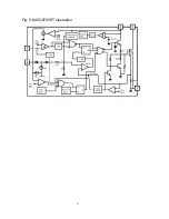
Pin36: EHT tracking/ overvoltage protection. If something is wrong, the anode high voltage rises, the 

eater voltage will rise too. When the rising voltage arrive some limit, the VD461 works, the 

oltage of pin 36 will exceed 3.9V, the N301will stop working. 

Pin37: PLL loop filter. 

Pin38: CVBS output. Monitor or RF videos can be selected.   

Summary of Contents for 21CTS92FS

Page 1: ...SERVICE MANUAL Model 21CTS92FS www akai ru COLOUR TV SET ...

Page 2: ...17 1 Technology Specification and Feature I2 C Bus Control Auto Search Off On Timer Teletext Rated Voltage AC 140V 250V 50Hz 60Hz Power Consumption 65 W Sound output 2 W 2 Screen size Picture tube 54 cm System RF PAL B G SECAM D K AV PAL NTSC 3 58 4 43 Channel coverage VHF Low channel VL 48 25 to 147 25 MHz VHF high channel VH 154 25 to 463 25 MHz UHF channel U 471 25 to 863 25 MHz IF 38 9MHz Exte...

Page 3: ... chips instruction 1 T c T TDA93X1 he UOC Ultimate One Chip TDA93X1 is adopted in this chassis This IC is the first available component that contains the complete ontrol and small signal functionality needed for a TV application in one device he UOC TDA93X1 pins function description total 64 pins Pin1 Standby control 1 is on 0 is off Pin2 SCL Pin3 SDA Pin4 Tuning PWM output Pin5 Auto AV control SW...

Page 4: ...resistor to ground The optimal reference current is 100mA which is determined by this resistor The 100mA reference current should not be changed ecause the geometry processor is optimised for this current Furthermore the output current of ertical drive and EW are proportional to this current Pin26 Vertical sawtooth This pin requires a capacitor to ground of 100nF Pin27 AGC output This output is us...

Page 5: ...signal output to the CRT board Pin54 3 3V Pin55 GND Pin56 3 3V Pin57 Pin58 Pin59 12MHz crystal Pin60 Reset NC in this chassis Pin61 3 3V Pin62 This pin is connected to the HEF4052 Functions expanding Pin63 This pin is connected to the HEF4052 Functions expanding Pin64 IR signal input 2 Memory AT24C08 is an E2 PROM of 8k pins describe as follows Pin1 Pin2 Pin3 Pin4 Pin7 GND Pin8 5V supply Pin5 SDA ...

Page 6: ...he TDA9859 is the audio effect processor the AN7522N is the driver The TDA9859 includes bass treble balance surround effect shortcut options Through Synchronous separating circuit the video signal is divided into orizontal Synchronizing signal and Vertical Synchronizing signal The horizontal Sync pulse coming from the pin 33 is ransferred to the horizontal drive transistor and will be used to driv...

Page 7: ... generator has a separate supply voltage of V on pin 6 On pin 4 a vertical guard signal is available For HF loop stability a damping resistor R407 is connected across the deflection coil 6 6 T Power supply he IC of KA5Q0765RT is adapted in this chassis it is the product of Fairchild It supplies four DC voltages one is the B 110V another is Hcc 26V the third is 13V the sound drive voltage the fourt...

Page 8: ...7 ...

Page 9: ...Fig 2 HEF4052BP illustration Fig 3 TDA8177 illustration 8 Thermal Protection AMP Pump up 1 INVERTING INPUT 5 VER OUTPUT 2 Vcc 6 OUTPUT STAGE VCC 3 PUMP UP OUT 7 NON INV PUT 4 GND ...

Page 10: ...Fig 4 AN17821A illustration 9 ...

Page 11: ...Fig 5 KA5Q0765RT illustration 10 ...

Page 12: ...11 Fig 6 TDA9859 illustration ...

Page 13: ...12 ...

Page 14: ...st VSHIFT value the center horizontal line correspond to CRT vertical center 3 Adjust Vamp value to get 90 of vertical picture contents would be displayed on CRT 4 Adjust HSHIFT value to get the picture horizontal center correspond to CRT horizontal center 5 Receive standard Crosshatch pattern signal for NTSC system and again adjust 7 3 MENU7 AGC TOP adjustment Receive 60dBu 1mv VH color bar signa...

Page 15: ...ow selection of narrow band sound PLL FFI ON OFF OFF Fast filter if PLL OSO ON OFF ON Switch off in vertical overscan FCO ON OFF OFF Compulsory colorful switch of weak signal WOOFER ON OFF OFF Have the heavy bass function choice switch of hour of TDA9860 DUAL OUT 0 1 1 Have the TDA9874 a track companion sound of hour to output Volume mode 0 1 1 One choice of the companion sound curve VOL PIN OPEN ...

Page 16: ...TXT DEF 0 3 0 The diagram text district constitution switch know well to see Note1 TXT BRI 0 32 8 A constitution of hour of the diagram text appearance TXT LIST 0 1 0 The diagram text fast index function constitution switch Know well to see the annotation 2 Note2 M4 SUBCON 0 63 36 Sub contrast SUBCOL 0 63 63 Sub colour SUBSHP 0 63 25 Pay the clear degree regulate SUBTINT 0 63 32 Pay the tone regul...

Page 17: ...nd curve 1 the recommendation be worth 20 SP16 0 63 52 2 spots of the companion sound curve 16 the recommendation be worth 35 SP32 0 63 56 2 spots of the companion sound curve 32 the recommendation be worth 45 SP48 0 63 58 2 spots of the companion sound curve 48 the recommendation be worth 60 START TIME 0 15 6 Switch on time constitution M8 VSLOPE 50HZ 34 60HZ 34 hight line position regulate VSHIF...

Page 18: ...nian Slovenian Czech Slovak Rumanian The EAST2 diagram text includes the following language Polish German Swedish Fin Dan Hungarian Lettish Russian Slovenian Czech Slovak Estonian Note 2 Make use of 4 color keys of the remote control browse 4 pages of the enactment quickly namely index function The TV AV sets the saving key for the index While using this function the TXT LIST establishes for ON in...

Page 19: ......

Reviews: