


HD10MD4 Mini-Converter v1.1r2 12 www.aja.com
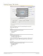
Colored text next to the connectors indicates the signal type and what the Mini-
Converter is doing:
• Blue text indicates the values automatically selected
• Black text indicates values that you have manually selected
• Red text indicates the Mini-Converter is not detecting a signal, or cannot
operate with the current user settings.
NOTE: Even if no output device is detected, the SDI connector text still shows the signal it
is outputting.
NOTE: Configuration settings in red will change based on the attached output device as
well as input signals. For improved accuracy and reliability, you should configure
the Mini-Converter only when the target output device is attached and input
signals are supplied at the inputs.
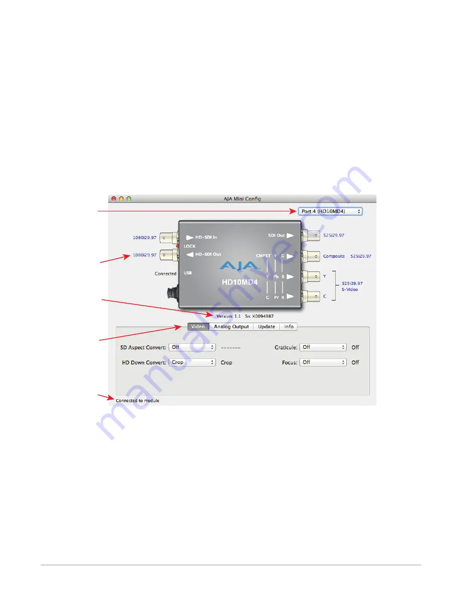
Screens are virtually the same on both PC and Mac, with subtle differences that
reflect the general look of the platform environment.
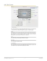
Figure 7. Example Mini-Config Screen
Select a USB port and
an attached
Mini-Converter (name
in parentheses).
Each connector is
labeled with the
signals currently
detected or manually
selected.
Firmware Version
and Serial Number
Status Message
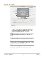
Tabbed Screens
Selecting a Mini-Converter with the pulldown menu causes this application to
connect to the selected converter. The graphic of Mini-Converter and text below
it provides:
• Type of converter
• Firmware version
• Serial number of the unit.
A status field at the bottom of the screen shows if your application is connected
and communicating with the Mini-Converter.
When configuring the Mini-Converter, select it from the top pulldown, view the
current settings and change any values. Making a change communicates that
new value to the Mini-Converter’s non-volatile memory.


