


-14-
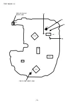
3. Confirmation of Sled movement
By pressing the F.SKIP or B.SKIP button continuously during the TEST MODE, it is possible to transfer the pick-up to either the outer
side or inner side.
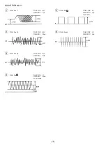
4. Confirmation of the RF level
Test point: RF and VC (Vref)
Test disc: TCD-782
Confirm that the RF waveform is as shown below.
VOLT/DIV: 200mV
TIME/DIV: 0.5us
5. Confirmation of Tracking balance
Test point: TE and VC (Vref)
Test disc: TCD-782
Press the DSL button while playing the test disc and confirm the TE waveform is as shown below.
VOLT/DIV: 200mV
TIME/DIV: 2ms
6. Confirmation of each servo
It is possible to confirm the adjustment value of each servo by repeatedly pressing the MODE button while the disc is playing.
The switchover sequence is as stated below.
Confirmation mode off
™
Focus Bias (FB)
™
Tracking Balance (TB)
™
Tracking Gain (TG)
™
Tracking Error Offset (TEO)
™
Focus Gain (FG)
™
Focus Error Offset (FEO)
™
Confirmation mode off
Example: Tracking Error Offset (TEO) Adjustment value: 03
* Adjustment value is displayed in HEX.
0.8Vp-p or more
A
B
VC
A:B=1:1
Tracking Error Offset (TEO) display
Adjustment value
TEST MODE-3/3
Summary of Contents for XP-V420
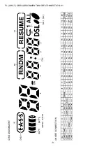
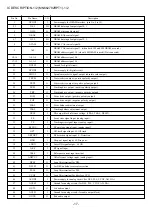
Page 8: ...8 FL AHC 7 GRID ASSIGNMENT ANODE CONNECTION 1 1 GRID ASSIGNMENT ANODE CONNECTION...
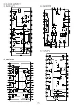
Page 9: ...9 SCHEMATIC DIAGRAM 1 1...
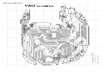
Page 10: ...10 WIRING 1 2 MAIN COMPONENT SIDE...
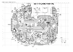
Page 11: ...11 WIRING 2 2 MAIN CONDUCTOR SIDE...
Page 26: ...26 CD MECHANISM EXPLODED VIEW 1 1 DA23LH 6 A C B 3 1 7 4 5 2 8...