background image

– 15 –

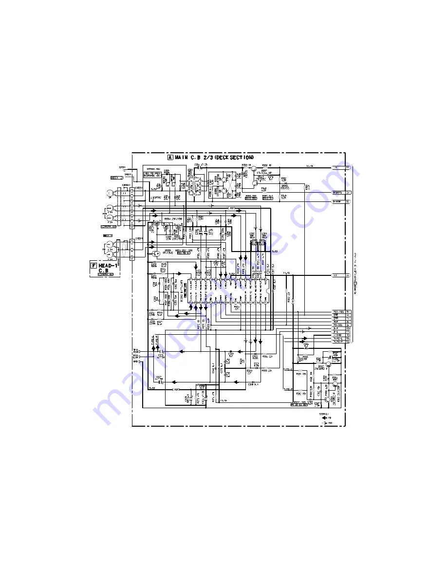
SCHEMATIC  DIAGRAM – 2  (MAIN : 2 / 3 <DECK  SECTION> / HEAD – 1)

Summary of Contents for NSX-VC38

Page 1: ...Code No 09 006 430 3R1 R E V I S I O N This Service Manual is the Revision Publishing and replaces Simple Manual NSX VC38 HR S M Code No 09 004 430 3T1 If requiring information about the CD mechanism see Service Manual of AZG 1 S M Code No 09 001 335 3NG NSX VC38 RC ZAS07 SYSTEM CD CASSEIVER REMOTE CONTROLLER CX NVC38 SPEAKER SX NBL25 ...

Page 2: ... range 87 5 MHz to 108 MHz Usable sensitivity IHF 13 2 dBf Antenna terminal 75 ohms unbalanced AM MW Tuner section Tuning range 531 kHz to 1602 kHz 9 kHz step 530 kHz to 1710 kHz 10 kHz step Usable sensitivity 350 µV m Antenna Loop antenna SW Tuner section HR only Tuning range 5 730 MHz to 17 900 MHz Usable sensitivity 40 µV IEC Antenna Wire antenna Amplifier section Power output Rated 40 W 40 W 6...

Page 3: ...US Laiteen Käyttäminen muulla kuin tässä käyttöohjeessa mainitulla tavalla saataa altistaa käyt täjän turvallisuusluokan 1 ylittävälle näkymättömälle lasersäteilylle VARNING Om apparaten används på annat sätt än vad som specificeras i denna bruksanvising kan användaren utsättas för osynling laserstrålning som överskrider gränsen för laserklass 1 PROTECTION OF EYES FROM LASER BEAM DURING SERVICING ...

Page 4: ...in power 2 2 2 2 2 Confirm that the main power is turned on and the HOLD terminal of the MICROCOMPUTER keeps the H level or not 3 3 3 3 3 When the HOLD terminal is L level the abnormality detection circuit is judged to be working correctly and the MICROCOMPUTER is judged to be good 1 Forced discharge of electrolytic capacitor of power supply block When repair is going to be attempted in the set th...

Page 5: ... ends of the electrolytic capacitor C113 that is connected to VDD of the MICROCOMPUTER with tweezers 3 3 3 3 3 Connect the AC power cord again If the MICROCOMPUTER returns to the normal operation the MICROCOMPUTER is good Note The reference number or MICROCOMPUTER pin number of transistor Q110 and electrolytic capacitor C113 can change depending on the models Be sure to check the reference numbers...

Page 6: ... C171 87 012 368 080 C CAP S 0 1 50 F C172 87 012 368 080 C CAP S 0 1 50 F C173 87 012 368 080 C CAP S 0 1 50 F C174 87 012 368 080 C CAP S 0 1 50 F C301 87 010 318 080 C CAP S 47P 50 CH C302 87 010 318 080 C CAP S 47P 50 CH C303 87 012 157 080 C CAP S 330P 50 CH C304 87 012 157 080 C CAP S 330P 50 CH C305 87 012 157 080 C CAP S 330P 50 CH C306 87 012 157 080 C CAP S 330P 50 CH C307 87 010 196 080...

Page 7: ...C CAP S 0 015 50 J B HR C790 87 A10 801 080 C CAP S 0 022 16 J B CM HS C791 87 010 196 080 CHIP CAPACITOR 0 1 25 C792 87 010 197 080 CAP CHIP 0 01 DM C793 87 010 404 080 CAP ELECT 4 7 50V C795 87 010 197 080 CAP CHIP 0 01 DM C796 87 010 197 080 CAP CHIP 0 01 DM C797 87 010 405 080 CAP ELECT 10 50V C798 87 010 197 080 CAP CHIP 0 01 DM C799 87 010 407 080 CAP ELECT 33 50V C800 87 010 194 080 CAP CHI...

Page 8: ...80 CAP CHIP 0 022 C154 87 010 246 040 CAP E 47 35 SME C155 87 010 404 040 CAP E 4 7 50 SME C156 87 010 404 040 CAP E 4 7 50 SME C361 87 010 178 080 CHIP CAP 1000P C362 87 010 178 080 CHIP CAP 1000P C371 87 010 178 080 CHIP CAP 1000P C372 87 010 178 080 CHIP CAP 1000P C401 87 010 186 080 CAP CHIP 4700P C402 87 010 112 040 CAP E 100 16 C403 87 010 545 040 CAP E 0 22 50 SME C404 87 010 320 080 CHIP C...

Page 9: ...200P C113 87 010 405 080 CAP ELECT 10 50V C114 87 010 405 080 CAP ELECT 10 50V C115 87 010 405 080 CAP ELECT 10 50V C116 87 010 405 080 CAP ELECT 10 50V C117 87 010 196 080 CHIP CAPACITOR 0 1 25 C119 87 010 197 080 CAP CHIP 0 01 DM C120 87 010 197 080 CAP CHIP 0 01 DM C133 87 010 197 080 CAP CHIP 0 01 DM C153 87 010 188 080 CAP CHIP 6800P C401 87 010 260 080 CAP ELECT 47 25V CN101 87 A61 011 010 C...

Page 10: ...OR ILLUSTRATION E C B CD1585 CSA952 CSC4115 KTA1266 KTC3198 B C E 2SA1235 2SC2714 2SC3052 CMBT5401 CMBT5551 2SK360 B C E 2SB1370 G D S 2SK2158 E C B DTC114ES KTC3199 D S G CSD1306 KRA104S KRC102S RT1P141C RT1P144C ...

Page 11: ... 11 FL HNA 10SS12 GRID ASSIGNMENT ANODE CONNECTION PIN CONNECTION GRID ASSIGNMENT ANODE CONNECTION PIN CONNECTION ...

Page 12: ... 12 WIRING 1 MAIN HR 10 11 12 13 14 15 16 17 18 19 20 21 22 23 24 A B C D E F G H I J K L M N O P Q R S T U 1 2 3 4 5 6 7 8 9 25 26 27 28 29 30 31 32 ...

Page 13: ... 13 WIRING 2 MAIN HS 10 11 12 13 14 15 16 17 18 19 20 21 22 23 24 A B C D E F G H I J K L M N O P Q R S T U 1 2 3 4 5 6 7 8 9 25 26 27 28 29 30 31 32 ...

Page 14: ... 14 SCHEMATIC DIAGRAM 1 MAIN 1 3 ...

Page 15: ... 15 SCHEMATIC DIAGRAM 2 MAIN 2 3 DECK SECTION HEAD 1 ...

Page 16: ... 16 SCHEMATIC DIAGRAM 3 MAIN 3 3 TUNER SECTION HR ...

Page 17: ... 17 SCHEMATIC DIAGRAM 4 MAIN 3 3 TUNER SECTION HS ...

Page 18: ... 18 WIRING 3 FRONT 10 11 12 13 14 15 16 17 18 19 20 21 22 23 24 A B C D E F G H I J K L M N O P Q R S T U 1 2 3 4 5 6 7 8 9 25 26 27 28 29 30 31 32 ...

Page 19: ... 19 SCHEMATIC DIAGRAM 5 FRONT DECK ...

Page 20: ... 20 WIRING 4 AMP 1F 10 11 12 13 14 15 16 17 18 19 20 21 22 23 24 A B C D E F G H I J K L M N O P Q R S T U 1 2 3 4 5 6 7 8 9 25 26 27 28 29 30 31 32 ...

Page 21: ... 21 SCHEMATIC DIAGRAM 6 AMP 1F ...

Page 22: ...WIRING 5 PT 22 1 2 3 4 5 6 7 8 9 10 11 12 13 14 15 A B C D E F G H I J K L M N O P Q R S T U ...

Page 23: ... 23 SCHEMATIC DIAGRAM 7 PT ...

Page 24: ...WIRING 6 DECK HEAD 1 24 1 2 3 4 5 6 7 8 9 10 11 12 13 14 15 A B C D E F G H I J K L M N O P Q R S T U ...

Page 25: ... 25 IC BLOCK DIAGRAM ...

Page 26: ... 26 ...

Page 27: ...utput 22 O CLOSE O CD tray close data output 23 O DISH_F O CD turntable forward rotation output 24 O DISH_R O CD turntable reverse rotation output 25 I O BUSY I O CD I O BUSY line 26 O STB O Strobe output for MAIN 27 I REA I Deck 2 side A recordable switch data input L REC 28 I RDS_CLK I Tuner RDS clock input Not used 29 I SUBQ I RDS_DATA I CD SUBQ data input Tuner RDS data input not used 30 RESET...

Page 28: ... P1 output DECK2 AUTO STOP switch data input 68 P2 I AUTO1 O I FL segment P2 output DECK1 AUTO STOP switch data input 69 P3 I CST2 O I FL segment P3 output DECK2 cassette detect switch data input 70 P4 I CST1 O I FL segment P4 output DECK1 cassette detect switch data input 71 P5 AM10K O I FL segment P5 output AM10K mode data input not used 72 P6 AMST O I FL segment P6 output AMST mode data input n...

Page 29: ...H as follows 9 FM SW O 2 BAND 3 BAND 3 BAND AM FM LW MW FM MW SW FM H L H H L H L L Outputs L or H as follows 10 MW SW O 2 BAND 3 BAND 3 BAND AM FM LW MW FM MW SW FM L L H L L L H L 11 IF MUTE O To control internal counter 12 IF IN I General purpose counter input 13 TUNE I Receives L when station is tuned 14 NC Not connected 15 AM IN I Receives the AM local oscillator frequency signal 16 FM IN I R...

Page 30: ...test point is more than 0 5V Then set to FM 108 0MHz and check that the test point is less than 8 0V 10 FM Tracking Check Settings Test point TP8 Lch TP9 Rch Method Set to FM 98 0MHz and check that the test point is less than 9dBµV 11 DC Balance Mono Distortion Adjustment Settings Test point TP3 TP4 DC Adjustment location L801 Input level 60dBµV Method Set to FM 98 0MHz and adjust L801 so that the...

Page 31: ...l 19 REC PB Sensitivity Check DECK 2 Settings Test tape TTA 602 Test point TP8 Lch TP9 Rch Input signal 1kHz 0VU 6dBV Method Apply a 1kHz signal and REC mode Then adjust OSC attenuator so that the output level at TP8 TP9 becomes 55mV 95mV Record and play back the 1kHz signals and check that the output is 2dB 3 5dB FRONT SECTION 20 µ CON OSC Adjustment Settings Test point TP11 KEY SCAN GND Adjustme...

Page 32: ... 32 CD TEST MODE ...

Page 33: ... 18 19 20 21 22 23 24 25 26 27 28 29 30 31 32 A A A A A I I E F A 6ZM 3 PR2NM PLATE EARTH MECHA PLATE EARTH MIC A D P C B FL901 37 34 35 42 41 46 43 A A A A A A F G A G A A J a a A B A K C F A D A I P C B CHAS MAIN 45 44 48 47 HT SINK 39 40 P C B HT SINK 38 33 P C B 36 AZG 1 VZD3RDM PT1 ...

Page 34: ... Color Basic color symbol Color B Black C Cream D Orange G Green H Gray L Blue LT Transparent Blue N Gold P Pink R Red S Silver ST Titan Silver T Brown V Violet W White WT Transparent White Y Yellow YT Transparent Yellow LM Metallic Blue LL Light Blue GT Transparent Green LD Dark Blue DT Transparent Orange GM Metallic Green YM Metallic Yellow DM Metallic Orange PT Transparent Pink 1 8A NF0 007 010...

Page 35: ...0 22 23 24 25 27 26 30 29 41 31 A A A A A A A A A I I F F E 6ZM 3 PR2NM PLATE EARTH MECHA PLATE EARTH MIC 28 P C B FL901 37 34 35 43 42 A A A A A A A F G A G A A H a a A B A J C D A H I P C B CHAS MAIN 45 44 47 46 HT SINK 39 40 P C B HT SINK VM 38 33 P C B 36 AZG 1 VZD3RDM BINDER WIRE PLATE SHLD 32 ...

Page 36: ... color symbol Color B Black C Cream D Orange G Green H Gray L Blue LT Transparent Blue N Gold P Pink R Red S Silver ST Titan Silver T Brown V Violet W White WT Transparent White Y Yellow YT Transparent Yellow LM Metallic Blue LL Light Blue GT Transparent Green LD Dark Blue DT Transparent Orange GM Metallic Green YM Metallic Yellow DM Metallic Orange PT Transparent Pink 1 8A NF0 007 010 WINDOW CASS...

Page 37: ...2 12 11 5 6 13 3 2 LEVER EJECT R LEVER EJECT L 27 48 53 52 51 57 54 55 56 63 62 49 50 59 P C B D D E F 38 39 40 32 34 33 35 43 45 41 41 44 16 18 47 30 46 8 B CAPSTAN N 2 2 41 7 P C B SOL 2 SOL 1 16 D A B C D A 15 A DECK L SIDE DECK R SIDE 36 42 24 C 37 A 58 CAPSTAN N 2 41 5 60 61 E F B E PLATE SHLD M3 C F G H ...

Page 38: ...M M2 33 82 ZM1 227 310 LVR TRIG 34 82 ZM3 306 110 LVR FR M2 35 82 ZM1 265 110 SPR E TRIG 36 87 761 073 410 VFT2 2 6 6 W O SLOT 37 82 ZM1 255 310 SPR E LVR DIR 38 82 ZM1 322 010 SPR T FR60 39 82 ZM1 220 210 GEAR IDLER 40 82 ZM3 616 010 RING MAGNET 4 41 82 ZM1 216 310 GEAR REEL 42 86 ZM3 213 010 S SCREW HLDR MOT 3 43 82 ZM1 225 210 GEAR FR 44 82 ZM1 226 010 GEAR REW 45 82 ZM3 333 310 SLIP DISK ASSY ...

Page 39: ...l click sound comes out Remove the grill frame and four pieces of rubber caps by pulling out with a flat bladed screwdriver Remove the screws from hole where installed rubber caps Insert a flat bladed screwdriver into the position indicated by the arrows and remove the panel Re move the screws of each speaker unit and then remove the speaker units TOOLS 1 Plastic head hammer 2 flat head screwdrive...

Page 40: ...SPKR W 140 5 8A NSK 606 010 SPKR T 60 6 87 NSH 612 010 SPKR CERAMIC ASSY 7 87 NS7 611 010 CORD SPKR ACCESSORIES PACKAGE LIST DESCRIPTION REF NO KANRI NO PART NO 1 8A NH0 901 010 IB H ECA M HR 2 87 006 226 010 AM LOOP ANT C0 HR 3 87 043 115 010 ANT FEEDER FM 4 87 A90 119 010 ANT WIRE SW 5M HR 5 87 050 103 010 CORD PIN 1PY1 5M 6 87 A91 017 010 PLUG CONVERSION JT 0476 HR 7 8Z NH8 702 010 RC UNIT RC Z...

Page 41: ...2 11 IKENOHATA 1 CHOME TAITO KU TOKYO 110 JAPAN TEL 03 3827 3111 Printed in Singapore 9420025 0251431 ...

Reviews: