
– 35 –
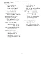
ADJUSTMENT 2 <TUNER / FRONT>
< FRONT SECTION >
1.
µ
-CON OSC Adjustment
Settings : • Test point :
TP1 (K-SCAN)
TP2 (GND)
• Adjustment location : L191
Method : Insert AC plug while pressing of "POWER" key and
"TUNER" function key. Connect a frequency across
TP1 and TP2. Then adjust L191 so that the frequency
across the test point is 208.8Hz
±
0.2Hz.
< TUNER SECTION >
1. Clock Frequency Check
Settings :
• Test point :
TP6 (CLK)
Method :
Set to AM 1710kHz and check that the test point is
2160kHz
±
45Hz.
2. AM VT Check
Settings :
• Test point :
TP3 (VT)
Method :
Set to AM 1710kHz and check that the test point is less
than 8.5V. Then set to AM 530kHz and check that the
test point is more than 0.6V.
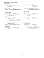
3. AM Tracking Adjustment
Settings :
• Test point :
TP6 (Lch), TP7 (Rch)
• Adjustment location : L951(1/3)
Method :
Set to AM 1000kHz and adjust L951(1/3) so that the
test point becomes maximum.
4. FM VT Adjustment
Settings :
• Test point :
TP3 (VT)
• Adjustment location : L906
Method :
Set to FM 108.0MHz and adjust L906 so that the test
point becomes 7.0V
±
0.1V. Then set to FM 87.5MHz
and check that the test point is more than 0.5V.
5. FM Tracking Adjustment
Settings :
• Test point :
TP6 (Lch), TP7 (Rch)
• Adjustment location : L903
Method :
Set to FM 87.5MHz and adjust L903 so that the test
point becomes maximum.
6. AM IF Adjustment
Settings :
• Test point :
TP6 (Lch), TP7 (Rch)
• Adjustment location :
L802 .................................................... 450kHz
7. DC Balance / Mono Distortion Adjustment
Settings :
• Test point :
TP4, TP5 (DC balance)
TP8 (Lch), TP9 (Rch)
(Mono distortion)
• Adjustment location : L801
• Input level :
60dB
µ
V
Method :
Set to FM 98.0MHz and adjust L801 so that the
voltage between TP4 and TP5 becomes 0V
±
500mV
with distortion less than 0.5%.
8. Output Level Check
<AM>
Settings :
• Test point :
TP6 (Lch), TP7 (Rch)
• Input level : 74dB
µ
V
Method :
Set to AM 1000kHz and check that the test point is
50mV
±
3dB.
<FM>
Settings :
• Test point :
TP6 (Lch), TP7 (Rch)
• Input level : 60dB
µ
V
Method :
Set to FM 98.0MHz and check that the test point is
150mV
±
3dB.
All manuals and user guides at all-guides.com
Summary of Contents for NSX-T929
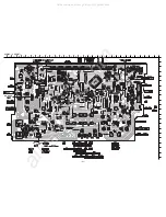
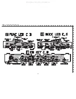
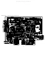
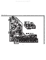
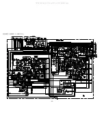
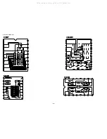
Page 15: ...15 SCHEMATIC DIAGRAM 1 MAIN 1 6 FUNCTION SECTION All manuals and user guides at all guides com...
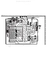
Page 17: ...17 SCHEMATIC DIAGRAM 3 MAIN 3 6 AMP SECTION All manuals and user guides at all guides com...
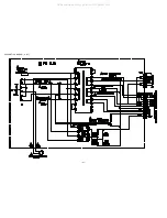
Page 19: ...19 SCHEMATIC DIAGRAM 5 MAIN 5 6 DSP SECTION All manuals and user guides at all guides com...
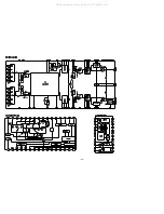
Page 20: ...20 SCHEMATIC DIAGRAM 6 MAIN 6 6 TUNER SECTION All manuals and user guides at all guides com...
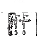
Page 25: ...25 SCHEMATIC DIAGRAM 8 AMP 1F VM All manuals and user guides at all guides com...
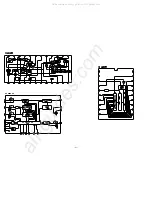
Page 27: ...27 SCHEMATIC DIAGRAM 9 PT All manuals and user guides at all guides com...
Page 29: ...29 IC BLOCK DIAGRAM All manuals and user guides at all guides com...
Page 30: ...30 All manuals and user guides at all guides com...
Page 31: ...31 All manuals and user guides at all guides com a l l g u i d e s c o m...
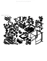
Page 37: ...37 MECHANICAL EXPLODED VIEW 1 1 All manuals and user guides at all guides com...