-37-
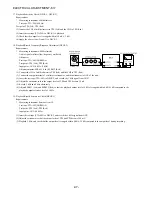
17.Playback Sensitivity Check (DECK 1, DECK 2)
Requirements
*
Measuring instrument: Millivoltmeter
Test tape: TTA-200 (400 Hz)
Test point: TP8 (Lch), TP9 (Rch)
(1) Connect the CH1 of millivoltmeter to TP8 (Lch) and the CH2 to TP9 (Rch).
(2) Insert the test tape (TTA-200) to DECK 1 to playback.
(3) Check that the output level is ranged within 110 mV
±
3 dB.
(4) Apply the above steps (2) and (3) to DECK 2.
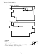
18.Playback/Record Frequency Response Adjustment (DECK 2)
Requirements
*
Measuring instruments: Millivoltmeter
Audio signal oscillator (low-frequency oscillator)
Attenuator
Test tape: TTA-602 (NORMAL)
Test point: TP8 (Lch), TP9 (Rch)
Input point: AUX (1 kHz / 8 kHz)
Adjustment point: SFR451 (Lch), SFR452 (Rch)
(1) Connect the CH1 of millivoltmeter to TP8 (Lch) and the CH2 to TP9 (Rch).
(2) Connect the output terminal of oscillator to attenuator, and then attenuator to AUX of the unit.
(3) Insert the test tape (TTA-602) to DECK 2, and record the 1 kHz signal from AUX.
(4) Adjust the attenuator so that the output levels of TP8 and TP9 become 10 mV.
(5) Record 1 kHz and 8 kHz alternately.
(6) Adjust SFR451 (Lch) and SFR452 (Rch) so that the playback output level of 8 kHz is ranged within 0 dB
±
1 dB compared to the
playback output reference level of 1 kHz.
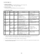
19.Playback/Record Sensitivity Check (DECK 2)
Requirements
*
Measuring instrument: Same as Item 18.
Test tape: TTA-602 (NORMAL)
Test point: TP8 (Lch), TP9 (Rch)
Input point: AUX (10 kHz)
(1) Insert the test tape (TTA-602) to DECK 2, and record the 1 kHz signal from AUX.
(2) Adjust the attenuator so that the output levels of TP8 and TP9 become 100 mV.
(3) Playback 1 kHz, and check that the output level is ranged within 0 dB
±
2.5 dB compared to the output level during recording.
ELECTRICAL ADJUSTMENT -6/7
Summary of Contents for NSX-R17
Page 25: ... 25 SCHEMATIC DIAGRAM 3 5 HP SECTION TO MAIN C B 1 2 AMP SECTION WH101 ...
Page 30: ... 30 SCHEMATIC DIAGRAM 5 5 PT SECTION TO MAIN C B 1 2 AMP SECTION WH001 ...
Page 40: ... 40 FL DISPLAY 1 1 HUA 13SS09T GRID ASSIGNMENT ANODE CONNECTION PINCONNECTION ...
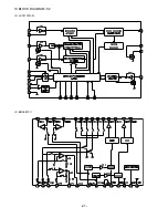
Page 41: ... 41 IC BLOCK DIAGRAM 1 2 IC LC72131D N IC BD3881FV ...
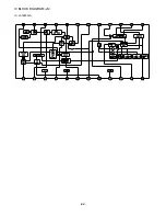
Page 42: ... 42 IC BLOCK DIAGRAM 2 2 IC LA1845N A ...
Page 53: ...2 11 IKENOHATA 1 CHOME TAITO KU TOKYO 110 8710 JAPAN TEL 03 3827 3111 0251431 ...


