background image

– 14 –

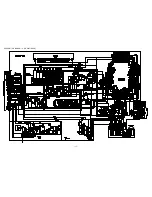
SCHEMATIC  DIAGRAM – 1  (MAIN : 1 / 2 <AMP  SECTION>)

Summary of Contents for NSX-AJ24 U

Page 1: ... and replaces Simple Manual NSX AJ24 U BL24 LH S M Code No 09 003 426 1T1 NSX BL23 LH BL34 LH S M Code No 09 004 426 1T4 NSX BL24 HS S M Code No 09 004 426 1T5 If requiring information about the CD mechanism see Service Manual of AZG 1 AZG 1 ZD8RDC S M Code No 09 001 335 3NA AZG 1 YZD8RDM S M Code No 09 001 335 3N6 AZG 1 ZD4RDC S M Code No 09 001 335 3N8 NSX AJ24 NSX BL23 NSX BL24 NSX BL34 NSX BL2...

Page 2: ... SPEAKER SX NAJ25 SX R140 NSX BL23 NSX BL24 NSX BL34 NSX BL24E NSX BL34E TAPE MECHANISM CD MECHANISM CX NAJ24 CX NBL23 CX NBL24 CX NBL34 CX NBL24E CX NBL34E SX NBL25 SX NBL42 SX NBL25 SX NBL42 ZZM 3 YPR1NC ZZM 3 YPR1NC ZZM 3 YPR1NM AZG 1 ZD8RDC AZG 1 ZD8RDC AZG 1 YZD8RDM AZG 1 ZD4RDC ...

Page 3: ... Tuner section Tuning range 87 5 MHz to 108 MHz Usable sensitivity IHF 13 2 dBf Antenna terminals 75 ohms unbalanced AM Tuner section Tuning range 530 kHz to 1710 kHz 10 kHz step 531 kHz to 1602 kHz 9 kHz step Usable sensitivity 350 µV m Antenna Loop antenna Amplifier section CX NAJ24 U Power output 50 W 50 W 50 Hz 20 kHz T H D less than 1 6 ohms 62 W 62 W 1 kHz T H D less than 10 6 ohms Total har...

Page 4: ...vändaren utsättas för osynling laserstrålning som överskrider gränsen för laserklass 1 PROTECTION OF EYES FROM LASER BEAM DURING SERVICING CAUTION Use of controls or adjustments or performance of proce dures other than those specified herin may result in hazardous radiation exposure ATTENTION L utillisation de commandes réglages ou procédures autres que ceux spécifiés peut entraîner une dangereuse...

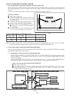
Page 5: ...in power 2 2 2 2 2 Confirm that the main power is turned on and the HOLD terminal of the MICROCOMPUTER keeps the H level or not 3 3 3 3 3 When the HOLD terminal is L level the abnormality detection circuit is judged to be working correctly and the MICROCOMPUTER is judged to be good 1 Forced discharge of electrolytic capacitor of power supply block When repair is going to be attempted in the set th...

Page 6: ... ends of the electrolytic capacitor C113 that is connected to VDD of the MICROCOMPUTER with tweezers 3 3 3 3 3 Connect the AC power cord again If the MICROCOMPUTER returns to the normal operation the MICROCOMPUTER is good Note The reference number or MICROCOMPUTER pin number of transistor Q110 and electrolytic capacitor C113 can change depending on the models Be sure to check the reference numbers...

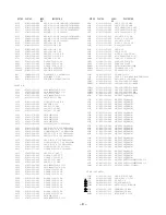
Page 7: ...25 M 85 24HS C22 87 A10 520 000 CAP E 3300 35 M SMG 23LH 24LH C22 87 A12 182 090 CAP E 3300 35 M85 24EHA 34LH 34EHA C25 87 010 385 080 CAP ELECT 220 25V C26 87 010 247 080 CAP ELECT 100 50V C30 87 010 430 080 CAP ELECT 100 63 C31 87 010 263 080 CAP ELECT 100 10V C32 87 010 197 080 CAP CHIP 0 01 DM C33 87 010 263 080 CAP ELECT 100 10V 24U C34 87 010 247 080 CAP ELECT 100 50V C35 87 010 380 080 CAP ...

Page 8: ...DM C796 87 010 197 080 CAP CHIP 0 01 DM C797 87 010 405 080 CAP ELECT 10 50V C798 87 010 197 080 CAP CHIP 0 01 DM C799 87 010 407 080 CAP ELECT 33 50V C800 87 012 369 080 C CAP S 0 047 50F C801 87 010 403 080 CAP ELECT 3 3 50V C802 87 010 194 080 CAP CHIP 0 047 C803 87 010 198 080 CAP CHIP 0 022 C804 87 010 263 080 CAP ELECT 100 10V C807 87 010 400 080 CAP ELECT 0 47 50V C808 87 010 401 080 CAP EL...

Page 9: ...906 87 010 322 080 C CAP S 100P 50 CH C907 87 010 322 080 C CAP S 100P 50 CH C908 87 010 322 080 C CAP S 100P 50 CH C909 87 010 322 080 C CAP S 100P 50 CH C910 87 010 322 080 C CAP S 100P 50 CH C911 87 010 178 080 CHIP CAP 1000P C912 87 010 196 080 CHIP CAPACITOR 0 1 25 C913 87 010 248 040 CAP E 220 10 SME C914 87 010 248 040 CAP E 220 10 SME C915 87 010 196 080 CHIP CAPACITOR 0 1 25 C916 87 010 1...

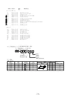
Page 10: ... PT ANF 9 HR HI 23LH 24LH 24EHA PT1 8A NF9 613 010 PT ANF 9 HR 24HS PT1 8A NF9 616 010 PT ANF 9 LH H 34LH 34EHA PT2 8A NF8 673 010 PT SUB ANF 8 H KAMI RY1 87 A91 339 010 RELAY AC DC12V GSPA 2 S1 87 A90 165 010 SW SL 1 2 3 SWS2301 23LH 24LH 24EHA 34LH 34EHA T1 87 A60 317 010 TERMINAL 1P MSC T2 87 A60 317 010 TERMINAL 1P MSC DECK C B CN1 87 099 753 010 CONN 11P H 9604 SFR1 87 024 581 010 SFR 3 3K H ...

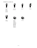
Page 11: ... E C B CD1585 CSA952 CSC4115 KTA1266 KTC3198 B C E 2SA1235 2SC2714 2SC3052 CMBT5401 CMBT5551 DTC114EK KRA102S KRC102S KRC104S RT1P141C RT1P144C E C B 2SC3331 S D G 2SJ460 2SK2541 B C E 2SB1370 G D S 2SK2158 E C B DTC114ES KTC3199 ...

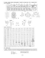
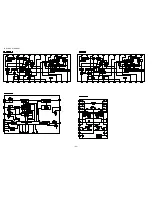
Page 12: ... 12 FL HNA 10SS12 GRID ASSIGNMENT ANODE CONNECTION PIN CONNECTION GRID ASSIGNMENT ANODE CONNECTION PIN CONNECTION ...

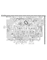
Page 13: ... 13 WIRING 1 MAIN 10 11 12 13 14 15 16 17 18 19 20 21 22 23 24 A B C D E F G H I J K L M N O P Q R S T U 1 2 3 4 5 6 7 8 9 25 26 27 28 29 30 31 32 ...

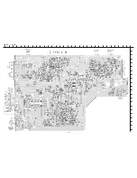
Page 14: ... 14 SCHEMATIC DIAGRAM 1 MAIN 1 2 AMP SECTION ...

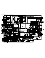
Page 15: ... 15 SCHEMATIC DIAGRAM 2 MAIN 2 2 TUNER SECTION ...

Page 16: ... 16 WIRING 2 FRONT 10 11 12 13 14 15 16 17 18 19 20 21 22 23 24 A B C D E F G H I J K L M N O P Q R S T U 1 2 3 4 5 6 7 8 9 25 26 27 28 29 30 31 32 ...

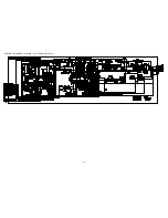
Page 17: ... 17 SCHEMATIC DIAGRAM 3 FRONT DECK ...

Page 18: ...WIRING 3 PT 24U ONLY 18 1 2 3 4 5 6 7 8 9 10 11 12 13 14 15 A B C D E F G H I J K L M N O P Q R S T U ...

Page 19: ... 19 SCHEMATIC DIAGRAM 4 PT 24U ONLY ...

Page 20: ...WIRING 4 PT EXCEPT 24U 20 1 2 3 4 5 6 7 8 9 10 11 12 13 14 15 A B C D E F G H I J K L M N O P Q R S T U ...

Page 21: ... 21 SCHEMATIC DIAGRAM 5 PT EXCEPT 24U ...

Page 22: ...13 14 15 16 17 18 19 20 21 22 23 24 A B C D E F G H I J K L M N O P Q R S T U 1 2 3 4 5 6 7 8 9 25 26 27 28 29 30 31 32 WIRING 5 DECK D DECK C B 1 3 5 7 9 11 2 4 6 8 10 1 3 5 7 9 11 FFC104 FROM B FRONT C B CN104 W1 ...

Page 23: ... 23 IC BLOCK DIAGRAM ...

Page 24: ...20 O POWER O System power supply ON OFF output 21 O OPEN O CD tray open data output 22 O CLOSE O CD tray close data output 23 O DISH_F O CD turntable forward rotation output 24 O DISH_R O CD turntable reverse rotation output 25 NC Not connected 26 NC Not connected 27 I REA I Deck 2 side A recordable switch data input L REC 28 I RDS_CLK I Tuner RDS clock input Not used 29 I SUBQ I RDS_DATA I CD SUB...

Page 25: ...C Not used 64 I TM_BASE I Base input for clock 65 I CAM2 I DECK2 CAM switch data input 66 I CAM1 I DECK1 CAM switch data input 67 P1 I AUTO2 O I FL segment P1 output DECK2 AUTO STOP switch data input 68 P2 I AUTO1 O I FL segment P2 output DECK1 AUTO STOP switch data input 69 P3 I CST2 O I FL segment P3 output DECK2 cassette detect switch data input 70 P4 I CST1 O I FL segment P4 output DECK1 casse...

Page 26: ...H as follows 9 FM SW O 2 BAND 3 BAND 3 BAND AM FM LW MW FM MW SW FM H L H H L H L L Outputs L or H as follows 10 MW SW O 2 BAND 3 BAND 3 BAND AM FM LW MW FM MW SW FM L L H L L L H L 11 IF MUTE O To control internal counter 12 IF IN I General purpose counter input 13 TUNE I Receives L when station is tuned 14 NC Not connected 15 AM IN I Receives the AM local oscillator frequency signal 16 FM IN I R...

Page 27: ...L951 1 3 Method Set to AM 1000kHz LH U HA AM 999kHz HS and adjust L951 1 3 so that the test point becomes maximum 4 AM IF Adjustment Settings Test point TP8 Lch TP9 Rch Adjustment location L802 450kHz 5 FM VT Check Settings Test point TP1 VT Method Set to FM 87 5MHz and check that the test point is more than 0 5V Then set to FM 108 0MHz and check that the test point is less than 8 0V 6 FM Tracking...

Page 28: ...the test tape and adjust screw so that the output becomes maximum Next perform on REV PLAY mode 12 PB Frequency Response Check DECK 1 DECK 2 Settings Test tape TTA 330 Test point TP8 Lch TP9 Rch Method Play back the 315Hz and 8kHz signals of the test tape and check that the output ratio of the 8kHz signal with respect to that of the 315Hz signal is 0dB 5dB 13 PB Sensitivity Check DECK 1 DECK 2 Set...

Page 29: ...ettings Test point TP11 KEY SCAN GND Adjustment location L951 Method Connect a frequency counter across TP11 and GND via a CR network filter as shown below Then adjust L951 so that the test point becomes 184 94Hz 0 18Hz ADJUSTMENT 2 FRONT IC901 FL901 GND TP11 KEY SCAN L951 C913 1 3 0 D981 1 FRONT C B B D989 D990 EXCEPT 24HS EXCEPT 24U ...

Page 30: ... 8 9 10 11 12 13 14 15 16 16 17 17 18 19 19 20 21 22 23 24 25 26 27 28 29 30 31 32 33 34 35 36 37 38 38 39 40 41 42 43 44 A A A A A C B A A A A A G G F F A A A A I I E F A AZG 1 ZD8RDC ZZM 3 YPR1NC CHAS MAIN PLATE EARTH HT SINK A D H P C B P C B P C B WIRE BINDER FL901 24LH ONLY ...

Page 31: ...mbol Color Basic color symbol Color Basic color symbol Color B Black C Cream D Orange G Green H Gray L Blue LT Transparent Blue N Gold P Pink R Red S Silver ST Titan Silver T Brown V Violet W White WT Transparent White Y Yellow YT Transparent Yellow LM Metallic Blue LL Light Blue GT Transparent Green LD Dark Blue DT Transparent Orange GM Metallic Green YM Metallic Yellow DM Metallic Orange COLOR N...

Page 32: ...15 16 16 18 17 17 19 20 21 22 23 24 25 26 27 28 29 30 31 32 33 35 36 34 37 37 38 39 40 41 42 43 A A A A A C B A A A A A G G F F A A A A I I E F A AZG 1 YZD8RDM 23LH AZG 1 ZD8RDC 34LH ZZM 3 YPR1NM 23LH ZZM 3 YPR1NC 34LH CHAS MAIN PLATE EARTH HT SINK A D H P C B P C B P C B WIRE BINDER FL901 23LH ONLY ...

Page 33: ...k C Cream D Orange G Green H Gray L Blue LT Transparent Blue N Gold P Pink R Red S Silver ST Titan Silver T Brown V Violet W White WT Transparent White Y Yellow YT Transparent Yellow LM Metallic Blue LL Light Blue GT Transparent Green LD Dark Blue DT Transparent Orange GM Metallic Green YM Metallic Yellow DM Metallic Orange COLOR NAME TABLE 1 8A NF0 007 010 WINDOW CASS 2 2 8A NF0 006 010 WINDOW CA...

Page 34: ...1 42 43 36 A A A A C B A A A A G G F A I AZG 1 ZD8RDC HT SINK H P C B P C B P C B WIRE BINDER FL901 4 5 6 10 7 11 12 13 15 20 18 18 21 25 27 26 32 33 34 I E F A A 1 2 3 7 8 14 16 16 17 17 PLATE EARTH MECHA C PLATE EARTH MIC D 44 45 F A A CHAS MAIN 30 A ZZM 3 YPR1NC 38 A A 9 19 ...

Page 35: ...y L Blue LT Transparent Blue N Gold P Pink R Red S Silver ST Titan Silver T Brown V Violet W White WT Transparent White Y Yellow YT Transparent Yellow LM Metallic Blue LL Light Blue GT Transparent Green LD Dark Blue DT Transparent Orange GM Metallic Green YM Metallic Yellow DM Metallic Orange COLOR NAME TABLE 1 8A NF0 007 010 WINDOW CASS 2 2 8A NF0 006 010 WINDOW CASS 1 3 8A NF0 004 010 BOX CASS 2...

Page 36: ...35 37 39 40 41 42 43 9 36 A A A A C B A A A A G G F A I AZG 1 ZD4RDC HT SINK H P C B P C B P C B WIRE BINDER FL901 4 5 6 10 7 11 12 13 15 20 18 18 21 25 27 26 32 33 34 I E F A A 1 2 3 7 8 14 16 16 17 17 PLATE EARTH MECHA C D 44 19 F A A CHAS MAIN 30 A ZZM 3 YPR1NC 38 A A ...

Page 37: ...k C Cream D Orange G Green H Gray L Blue LT Transparent Blue N Gold P Pink R Red S Silver ST Titan Silver T Brown V Violet W White WT Transparent White Y Yellow YT Transparent Yellow LM Metallic Blue LL Light Blue GT Transparent Green LD Dark Blue DT Transparent Orange GM Metallic Green YM Metallic Yellow DM Metallic Orange COLOR NAME TABLE 1 8A NF0 007 010 WINDOW CASS 2 2 8A NF0 006 010 WINDOW CA...

Page 38: ... 10 11 10 11 12 12 13 13 14 14 15 15 16 16 17 18 18 19 19 20 20 21 21 30 22 23 24 25 26 27 28 22 23 24 25 26 27 28 29 31 32 33 34 35 36 37 37 38 38 39 39 40 41 42 43 44 51 52 45 46 47 48 49 50 53 54 54 56 55 30 35 29 31 32 33 52 51 44 45 43 42 IC EW732 IC EW732 b a a b c c 40 41 46 47 48 49 P C B ...

Page 39: ... C FR M3 26 8Z ZM3 250 010 GEAR SLIP F R A M3 27 8Z ZM1 269 010 FELT FF REW 2 28 8Z ZM1 238 110 GEAR SLIP FF REW B 2 29 8Z ZM3 220 010 LEVER FR M3 30 8Z ZM3 205 010 LEVER PLAY M3 31 8Z ZM3 233 010 SPR T BRG M3 32 84 ZM2 227 310 SPR C AZIMUTH 33 87 A90 403 110 HEAD RPH MS15R 34 87 A90 404 010 HEAD EH LE15B 35 8Z ZM3 239 010 SPR E FR 36 8Z ZM3 211 010 LEVER EJECT R 37 8Z ZM3 225 010 LEVER STOP 38 8Z...

Page 40: ...l click sound comes out Remove the grill frame and four pieces of rubber caps by pulling out with a flat bladed screwdriver Remove the screws from hole where installed rubber caps Insert a flat bladed screwdriver into the position indicated by the arrows and remove the panel Re move the screws of each speaker unit and then remove the speaker units TOOLS 1 Plastic head hammer 2 flat head screwdrive...

Page 41: ...KR T 60 5 87 NSH 612 010 SPKR CERAMIC ASSY 6 87 NS7 611 010 CORD SPKR ACCESSORIES PACKAGE LIST DESCRIPTION REF NO KANRI NO PART NO 1 8A NF0 902 010 IB LH ESP FM BL24 BL34 24LH 34LH 24EHA 34EHA 1 8A NF0 903 010 IB U ESF FM AJ24 24U 1 8A NF0 922 010 IB LH P CCE BL24J 23LH 2 87 006 225 010 ANT LOOP ANT NC2 23LH 2 87 A90 030 010 ANT LOOP AM NC C EXCEPT 23LH 3 87 043 115 010 FEEDER ANT FM 4 87 A91 017 ...

Page 42: ...2 11 IKENOHATA 1 CHOME TAITO KU TOKYO 110 JAPAN TEL 03 3827 3111 Printed in Singapore 9420025 0251431 ...

Reviews: