


32
__________
I-STOP
COM0-COM3
I-INIT
______
I-AC/DC
VSS3
VDD3
O-NC
O-TUCE
O-CD-ON
_____________
O-TU-ON
__________
O-RMT
________ _____
O-REC/PB
O-MUTE
O-PCONT
__________
O-BIAS
O-NC
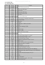
Pin No.
Pin Name
I/O
Description
82
83-86
87
88
89
90
91
92
93
94
95
96
97
98
99
100
I
O
I
O
—
—
O
O
O
O
O
O
O
O
O
O
Tape stop input.
LCD common output.
Initial setting input.
Beat selector output. “H” during selection. CMOS output .
GND.
5V.
Not used.
Tuner chip enable output. CMOS output .
“H” output during CD function. CMOS output.
“H” output during TU function. Open drain output.
REC mute output. “H” during mute. Open drain output.
REC/PB select output. “H” during PB. Open drain output.
Mute output. “H” during mute. Open drain output.
Power control output. “H” at ON. CMOS output.
REC bias ON/OFF output. “H” at ON. Open drain output.
Not used.
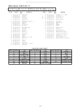
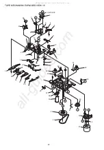
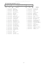
All manuals and user guides at all-guides.com
Summary of Contents for LCX-157 HS
Page 14: ...22 21 SCHEMATIC DIAGRAM 3 FRONT IRDDT IR200 All manuals and user guides at all guides com ...
Page 15: ...24 23 SCHEMATIC DIAGRAM 4 CD All manuals and user guides at all guides com ...
Page 16: ...26 25 VOLTAGE CHART All manuals and user guides at all guides com a l l g u i d e s c o m ...
Page 17: ...28 27 All manuals and user guides at all guides com ...
Page 18: ...30 29 ELECTRICAL ADJUSTMENT All manuals and user guides at all guides com ...


