background image

8

Marvair Classic AVPA/HVPA/HVPSA Heat Pump I&O Manual

11/2017 Rev. 7

How It Works

During the summer, cool dry air from the classroom is exhausted through the GreenWheel

®

 ERV to the 

outside. As the air passes through the rotating wheel, the desiccant becomes cooler and drier. Simultaneously, 

hot humid air is being pulled across the rotating wheel. The cool, dry desiccant absorbs moisture and 

heat from the incoming air. The cooler, drier air is mixed with the return air from the classroom and 

distributed throughout the room.
In the winter, warm moist air is exhausted through the GreenWheel

®

 ERV to the outside. As the air passes 

through the rotating wheel, the desiccant becomes warmer and absorbs moisture. Simultaneously, cold 

dry air is being pulled across the rotating wheel. The cold, dry air absorbs heat and moisture from the 

desiccant. The warmed air is mixed with the return air from the classroom and distributed throughout 

the room.

Quality Components 

The GreenWheel

®

 module consists of a desiccant wheel, two blowers and the drive motor and belt.  The 

two blowers simultaneously pull fresh air from outside and exhaust air from the classroom through the 

rotating wheel. Two variable speed blowers ensure that up to 450 CFM of outside air can be brought into 

the room and the indoor air is properly exhausted. Variable speed blowers permit that the desired quantity 

of outside air is delivered into the room. Optional independent exhaust air blower control allows positive 

pressurization of the classroom, i.e., more outside air can be introduced through the GreenWheel

®

 ERV 

than is exhausted.

GreenCube

®

 ERV (Ventilation Option “Q”)

The GreenCube ERV is an enthalpy plate heat exchanger that transfers both sensible and latent energies 

between outgoing and incoming air streams in a cross flow arrangement. Except for two air movers, it has 

no moving parts. The media is impregnated with a RC134 polymeric desiccant that exchanges water by 

direct vapor transfer using molecular transport without the need of condensation. The GreenCube

®

 ERV 

will operate at temperatures as low as 10°F without a defrost mechanism. In addition, the desiccant is a 

bactericide. Two MERV 6 type filters are used on both sides of the enthalpy core. The fresh air and exhaust 

motors have independent speed controllers to permit each of the motors to be regulated independently.
The GreenCube

®

 ERV is available in heat pumps with nominal cooling capacities of 24,000 through 

60,000 BTUH. See the Marvair Classic product data sheet for cabinet dimensions..

Hot Gas Reheat (HGR) Dehumidification Mode (Special Option “G”)

When the HGR is in the dehumidification mode, the hot gas reheat (HGR) coil is energized. The cooled, 

dehumidified air exits the evaporator coil and is blown through the HGR coil. This coil is sized to the 

sensible capacity of the unit. The heat in the HGR coil is transferred to the air stream. The use of the HGR 

coil allows the indoor humidity of the classroom to be maintained at or below a certain set humidity set 

point without over cooling the classroom. These units can not add humidity to the classroom.
The operation of the HGR coil is controlled by a humidity controller. If the humidity rises above the set 

point on the controller and the temperature in the classroom is satisfied, both mechanical cooling and 

the HGR coil operate to temper the air and lower the humidity. If the temperature in the classroom rises 

above or falls below the set point of thermostat and the unit is operating in the dehumidification mode, 

the need for cooling or heating will override the call for dehumidification and the HGR coil is disengaged 

until the thermostat is satisfied. This assures the classroom temperature is maintained as first priority 

and humidity control is second.
The humidity controller or BAS control is required for proper operation of the HGR coil.

Summary of Contents for Marvair AVPA 24

Page 1: ...d options this unit is equipped with INSTALLER Affix the instructions on the inside of the building adjacent to the thermostat END USER Retain this manual for future reference Heat Pump Product Manual...

Page 2: ...ing any work Failure to follow these rules may result in death serious bodily harm property damage and damage to the equipment Important Safety Precautions 1 USE CARE when LIFTING or TRANSPORTING equi...

Page 3: ...Set Up 30 Chapter 4 Troubleshooting 4 1 Overview 32 4 2 Failure Symptoms Guide 33 4 3 Compressor Troubleshooting 34 4 4 Electric Heat Control 35 Chapter 5 Electrical Schematics 5 1 Electrical Schemat...

Page 4: ...r Adjustment 30 Figure 9 Damper Air Path 31 Figure 10 Typical Configuration for Single Element Heater 35 Figure 11a Typical 1 Electrical Schematic Diagram Heat Pump Models AVPA with Manual Outside Air...

Page 5: ...r ventilation packages and the economizer are non removable factory installed and tested Instructions for the HVP models with the GreenWheel ERV and the GreenPac HGR are included in this manual AllAir...

Page 6: ...at 230v Air flow ratings of 480 v units are at 460 volts Operation of units at a different voltage from the rating point will affect air flow Table 1b Air Flow Cubic Feet per Minute HVPA HVPSA MODEL...

Page 7: ...released into the room The compressed refrigerant vapor will condense to its liquid state as it gives up heat Finally liquid flows through a metering device into the evaporator where the cycle will b...

Page 8: ...rs it has no moving parts The media is impregnated with a RC134 polymeric desiccant that exchanges water by direct vapor transfer using molecular transport without the need of condensation The GreenCu...

Page 9: ...EH will be energized when a 24 VAC signal is applied to the W2 terminal The control will monitor the status of the loss of charge switch and the high pressure switch If either of these inputs recogni...

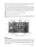
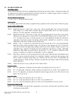
Page 10: ...otentiometers pots that allow the user to select settings to optimize the installation See Figure 1 for location of the pots Delay on Make The control has a pot settable 0 03 to10 minute delay on make...

Page 11: ...he EHDD function will be disabled S Circuit The S Circuit prevents the compressor and electric heat from operating simultaneously The S Circuit is pin selectable using a jumper to select Yes to enable...

Page 12: ...condition will only be reset by manually cycling power to the control To reset the switch turn primary power off then back on or turn thermostat system switch off then back on The loss of charge switc...

Page 13: ...switch terminals are the loss of charge switch input DS The DS terminals are the defrost sensor input CS The CS terminals are the coil sensor optional input This input will monitor the condenser coil...

Page 14: ...s achieved by operating mechanical cooling in conjunction with a hot gas reheat coil The coil is sized approximately to the sensible capacity of the total tonnage of the machine Speed Control for Gree...

Page 15: ...e outdoor ambient is too hot or humid the sensor will place the actuator in the closed or minimum open position and activate mechanical cooling The compressor is locked out during the economizer cooli...

Page 16: ...nd for 24 hours with primary power turned on 2 Attempt to start the compressor after 24 hours 3 If the compressor will not start makes excessive noise or will not operate return the unit to the freigh...

Page 17: ...e minimum clearances required for proper operation and service Tables 4a 4b below MODEL Min Clearance From the Front Min Clearance Around Sides Single Unit Min Clearance Between Sides Two Units Min Sp...

Page 18: ...hree stage heat Three stage cool Manual or auto changeover Fan Auto On Ten year retention of programming settings and 48 hour clock and day settings on power loss Adjustable max setpoint for heating a...

Page 19: ...rk WARNING FIRE HAZARD Improper adjustment alteration service maintenance or installation could cause serious injury death and or property damage Installation or repairs made by unqualified persons co...

Page 20: ...ient quantity of supply registers adequate return and filter area Ductwork must be of correct material and must be properly insulated Ductwork must be constructed of galvanized steel with a minimum th...

Page 21: ...match this opening Allow sufficient clearance to run 3 4 conduit through the hole and to the unit 2 Apply a bead of silicone sealer on the wall side of the mounting brackets on the Heat Pump Circle th...

Page 22: ...by qualified persons CAUTION This Classic Heat Pump may incorporate an internal crankcase heater for compressor protection The crankcase heater must be energized for at least 24 hours prior to startin...

Page 23: ...hase compressors in the reversed direction for a short duration of time usually defined as less than one hour However after several minutes of operation the compressor s internal protector will trip T...

Page 24: ...X H E R A Y O W2 G C R A Y O HEAT PUMP LOW VOL TAGE SECTION Thermostat Field Supplied Seven 7 Conductor Color Coded 18 Gauge Thermostat Cable Humidity Controller A C s do not have O Figure 5a Humidit...

Page 25: ...ostat Slowlylowerthethermostatcoolingsetpointtemperature Once the indoor fan turns on allow approximately three minutes for the compressor and outdoor fan to start For units equipped with the low ambi...

Page 26: ...pump with economizer and all HVP models option on all other Classic units has cycled 3 Move the system switch to the Off position All functions should stop The Blower Timed Delay Relay BTR keeps the b...

Page 27: ...erature F Insert the probes of the meter into the negative black and positive red set point test terminals on the board Carefully and in small increments turn the blue knob on the potentiometer until...

Page 28: ...Subtract the return air from the supply air The difference is the amount of fresh air c Loosen the set screw that holds the collar onto the rod connected to the damper Move the collar and tighten the...

Page 29: ...lue of the Tmix equals the calculated or desired value of Tmix The motorized damper Configuration B can be controlled by an optional relay that allows additional external control with a choice of 24 1...

Page 30: ...rds and practices Adjust the speed of the intake air GreenCube ERV blower until the required outside air is being brought into the classroom c Next measure the exhaust air from the classroom Adjust th...

Page 31: ...Unit does not run NOTE An internal anti short cycle timer will prevent the unit from starting for 2 to 8 minutes following start up 1 Power supply problem 2 Tripped internal disconnect 3 Shut off by...

Page 32: ...wiring and sche matic diagrams Test components especially the compressor for shorts 4 Note voltage range limitations specific to the compressor troubleshooting section E Water on floor near unit 1 Obs...

Page 33: ...r Single Element Heater The electric heater assembly can have up to three individual heating elements Each individual heating element is protected against overheating by its own dual function thermal...

Page 34: ...n are energized with a contactor controlled by a 24 VAC pilot signal The condenser outside fan motor is energized by the same contactor However the motor is cycled on and off by the low ambient contro...

Page 35: ...35 Marvair Classic AVPA HVPA HVPSA Heat Pump I O Manual 11 2017 Rev 7 Figure 11a Typical 1 Electrical Schematic Diagram Heat Pump Models AVPA with Manual Outside Air Damper...

Page 36: ...36 Marvair Classic AVPA HVPA HVPSA Heat Pump I O Manual 11 2017 Rev 7 Figure 11b Typical 208 230v 3 Electrical Schematic Diagram Heat Pump Models AVPA...

Page 37: ...37 Marvair Classic AVPA HVPA HVPSA Heat Pump I O Manual 11 2017 Rev 7 Figure 11c Typical 460v 3 Electrical Schematic Diagram Heat Pumps Models AVPA with the PC Control Board...

Page 38: ...38 Marvair Classic AVPA HVPA HVPSA Heat Pump I O Manual 11 2017 Rev 7 Figure 11d Typical Electrical Schematic Diagram Heat Pump Models HVPA with Manual Outside Air Damper...

Page 39: ...39 Marvair Classic AVPA HVPA HVPSA Heat Pump I O Manual 11 2017 Rev 7 Figure 11e Typical Electrical Schematic Diagram Heat Pump Models HVPA with Economizer...

Page 40: ...wet any of the electrical components Be sure the unit has dried before restarting Use a fin comb of the correct spacing to straighten mashed or bent fins Outdoor Coil Periodically inspect the outdoor...

Page 41: ...y operating or staging the unit in a corrosive environment 4 Damages caused by improper application of the product 5 Damages caused by failing to perform proper routine maintenance 6 Expenses incurred...

Page 42: ...bilities specific instructions will not be given When in doubt follow standard and accepted installation practices or contact Marvair for additional assistance Wall Openings Measure the dimensions of...

Page 43: ...ole on far end Make sure stem of new heater assembly is inserted into correct hole The hole nearest to the indoor coil is for three element heaters and the farthest away from indoor coil is for all ot...

Page 44: ...44 Marvair Classic AVPA HVPA HVPSA Heat Pump I O Manual 11 2017 Rev 7...

Reviews: