background image

Sprint Voice Pro Installation Guide  

DUG01610-SP


Airspan Commercial and Internal Use 

1. 

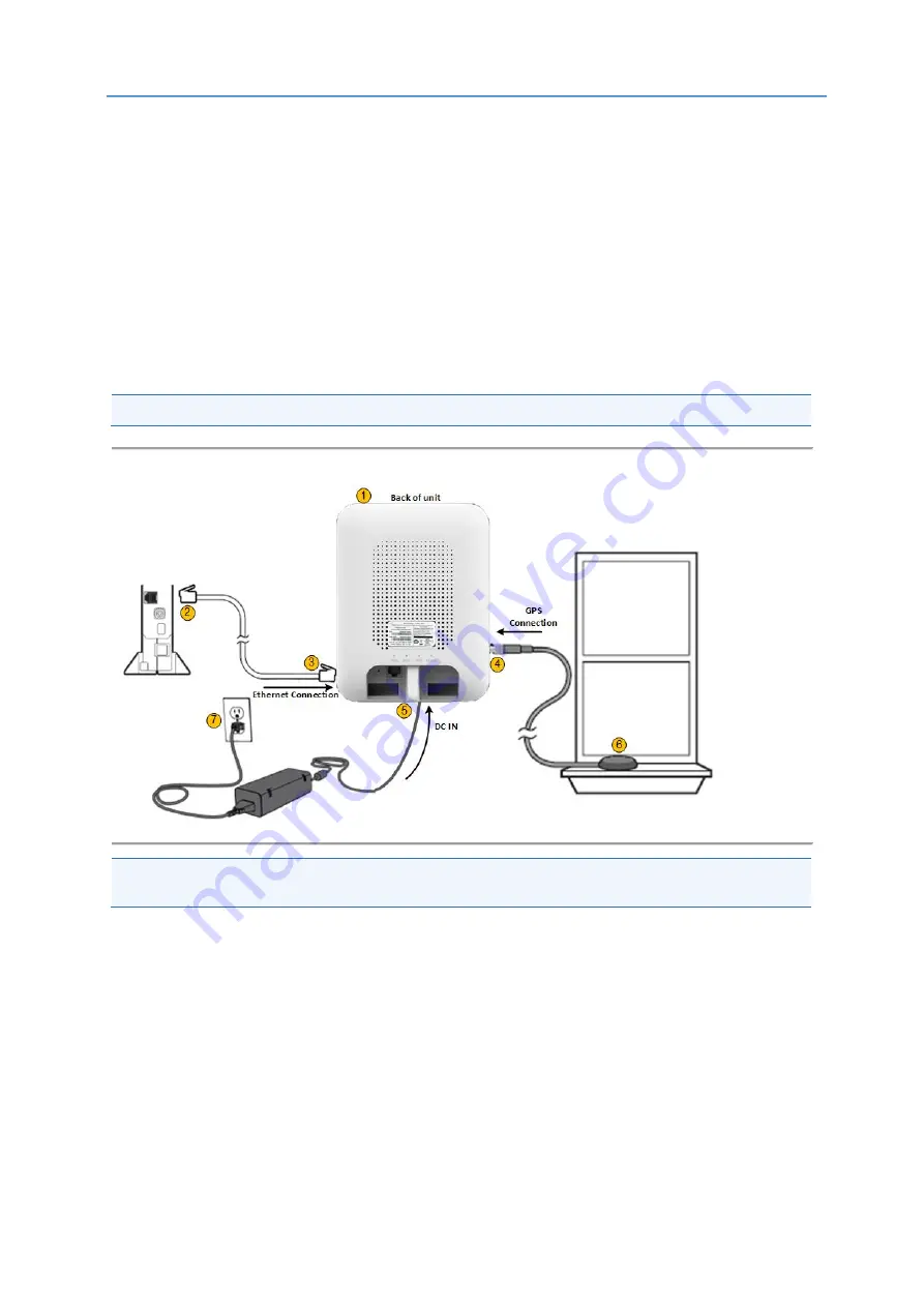
Turn the Voice Pro unit to expose the back of the unit. 

2. 

Connect one end of the Ethernet cable to an available LAN port on your broadband 
connection modem, or to a LAN port on your network. If on network: 


Open UDP ports 53, 67, 500 and 4500 bi-directionally 


Contact your IT administrator for assistance  

3. 

Place the other end of the Ethernet cable in the unit’s Ethernet port. 

4. 

Connect the External GPS antenna to the GPS connection port on the side of the Sprint 
Magic Box Voice Pro, under the cap.


5. 

Plug the power supply cable into the DC IN port on the back of the unit.


6. 

Place the GPS antenna base on a flat surface next to a closed window.


7. 

Plug the other end of the power supply unit into an available electrical outlet.


Note:

 A surge protected outlet is recommended. 


Figure 3: Sprint Voice Pro Connections 


Note:

 The Sprint Voice Pro must be connected to the Sprint network in order for the Sprint Voice 

Pro to work. 


Summary of Contents for Sprint Voice Pro

Page 1: ...Sprint Voice Pro Installation Guide Part Number DUG01610 SP System Release 16 0 Revision A Published August 2019 ...

Page 2: ... without limitation the accuracy or completeness of any information facts and or opinions contained therein No responsibility is assumed by Airspan Networks Ltd for the use of the documents nor for the rights of third parties which may be effected in any way by the use thereof The provision of these documents and the documents themselves does not constitute professional advice of any kind Any repr...

Page 3: ...sk 4 Airspan Encourages Comments 4 1 Overview 5 2 Installing the Sprint Voice Pro 6 2 1 Check the Contents 6 2 2 Where to Place the Unit 6 2 3 Installing the Sprint Voice Pro 7 3 Troubleshooting Sprint Voice Pro 9 4 FCC Statement 10 5 UL Authorization Statement 11 Figures Figure 1 Sprint Voice Pro 6 Figure 2 Voice Pro Back 7 Figure 3 Sprint Voice Pro Connections 8 Tables Table 1 LED Display 9 ...

Page 4: ...2 Document Information Abstract This document details a description of the connection scenario of the Sprint Voice Pro AVC unit Revision History Revision Details Date Summary of Changes 0 1 January 2019 Initial draft document comments A August Changed document name part number Publish ...

Page 5: ...al Use 3 About This Document Purpose This Installation Guide is intended as an instructional manual to provide step by step instructions for installation of the Sprint Voice Pro AVC Intended Audience This guide is intended for persons who are installing the Sprint Voice Pro unit ...

Page 6: ...sends an issue number for your reference The system uses this issue number to categorize and store e mails under the appropriate issue To help Customer Care Help Desk identify your issue include the issue number and your Customer Care Helpdesk account details in all further communications Main Operations Airspan Communications Ltd Capital Point 33 Bath Road Slough Berkshire SL1 3UF United Kingdom ...

Page 7: ...ce Pro Installation Guide DUG01610 SP Airspan Commercial and Internal Use 5 1 Overview The Sprint Voice Pro enables voice via CDMA This installation guide is intended to explain how to connect the Voice Pro unit ...

Page 8: ...t Voice Pro open the box and 1 Carefully remove the Sprint Voice Pro from its packaging 2 Check that all the components are in the box Voice Pro unit Ethernet cable External GPS Antenna Power Supply unit Figure 1 Sprint Voice Pro 2 2 Where to Place the Unit The optimal position to place the Voice Pro is as listed below In an elevated location such as the top of a shelf or tall cabinet Within 10 to...

Page 9: ...Voice Pro Installation Guide DUG01610 SP Airspan Commercial and Internal Use 7 2 3 Installing the Sprint Voice Pro Follow these step by step instructions to install the Sprint Voice Pro Figure 2 Voice Pro Back ...

Page 10: ...other end of the Ethernet cable in the unit s Ethernet port 4 Connect the External GPS antenna to the GPS connection port on the side of the Sprint Magic Box Voice Pro under the cap 5 Plug the power supply cable into the DC IN port on the back of the unit 6 Place the GPS antenna base on a flat surface next to a closed window 7 Plug the other end of the power supply unit into an available electrica...

Page 11: ...re than 15 minutes Contact Sprint Blinking Red CDMA IPSec tunnel is establishing a connection Blinks as long as tunnel still establishing Tunnel have gone down for less than 15 minutes Wait Off SW Loading GPS Solid Green GPS device has acquired a lock and is ready None Solid Red GPS error GPS has not achieve fix since Boot up 30 minutes or more Verify external antenna is connected and located clos...

Page 12: ...following measures Reorient or relocate the receiving antenna Increase the separation between the equipment and receiver Connect the equipment into an outlet on a circuit different from that to which the receiver is connected Consult the dealer or an experienced radio TV technician for help FCC Compliance Statement Part 15 19 This device complies with Part 15 of the FCC Rules Operation is subject ...

Page 13: ...end a copy of this notice to each manufacturing location currently authorized under File E199598 Vol X2 Records in the Follow Up Services Procedure covering the product are now being prepared and will be sent in the near future Until then this letter authorizes application of the UL Mark for 90 days from the date indicated above Additional requirements related to your responsibilities as the Appli...

Reviews: