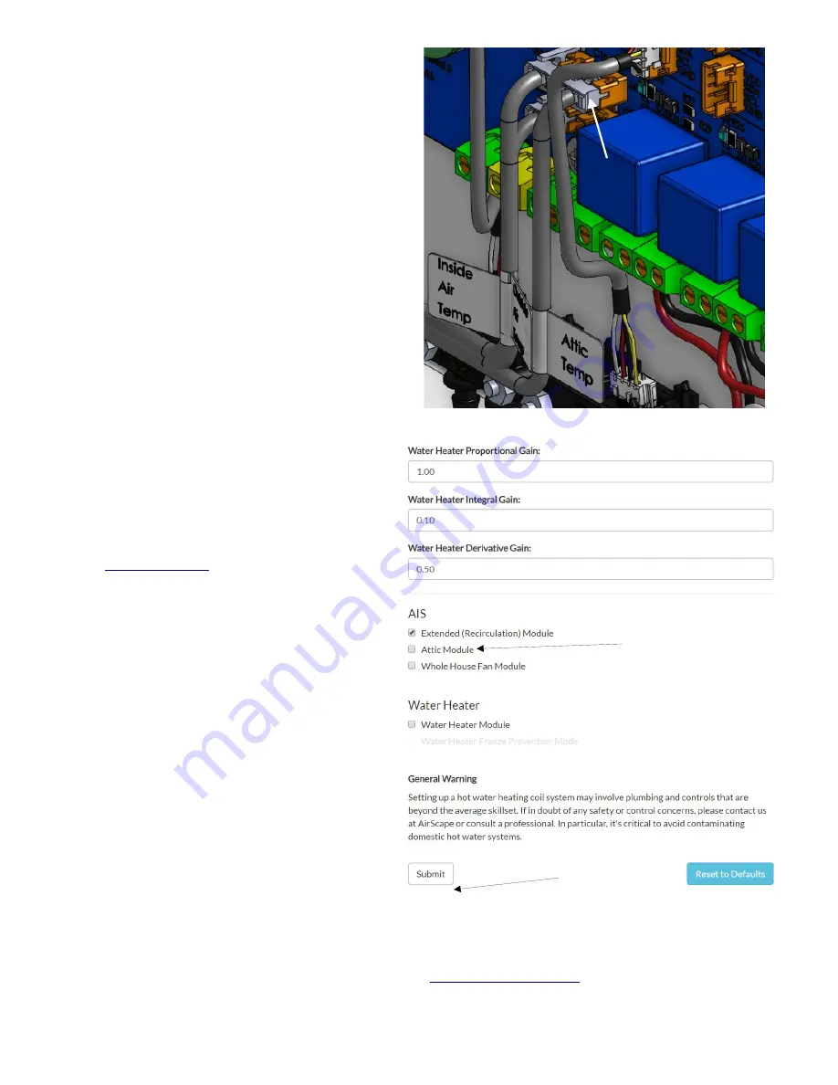
Remove the strain relief holding two temperature
harnesses to the side wall of the control box. Route
the included Attic Temperature sensor through the
same opening and connect the connector as shown
to J4 on the blue main board. Make sure there is a
little slack in the temp sensor harnesses and reinstall
the strain relief on the outside of the box.
The head or black tip of temperature sensor needs to
be in the attic and so leave it in safe spot.
In order to activate and control the Heat Assist
Module the added ability has to be unlocked in the
controller.
This is done via a web browser on any computer,
tablet or smartphone that is connected to the same
Local Area Network (LAN) as the MUA unit.
Make sure the MUA unit is on and connected to
the network router via Cat-5 cable. Open a web
browser on any device that is connected to the
same network as the MUA unit. In the URL
Address Bar of the browser, type in the IP Address
of the MUA Unit and allow the window to load.
(See
and it’s “tip” if it does not
work)
If the page loads and the MUA interface is up
enter the address bar and at the end of the IP
address add /config and press enter.
(like: 192.168.10.3
/config
)
The Factory Settings page should now be up.
On the right hand bottom of the page there are
some check boxes (see image)
Click the “Attic Module” check box
Select “Attic-conf”
(on the RH top of the page)
Click the “Submit” Button
this completes the activation of the Heat Assist
Module
Go back to the main MUA unit page by clicking on
the “Back to Main Page” button.
You can also click in the IP Address in the URL Address Bar and by simply deleting the /config portion of the
address and by pressing Enter you reactivate the main interface.
Perform an operational test of the Heat Assist box (see
© AirScape MUA-IOM, July 2022, All Rights Reserved.
12
Click
“Attic Module”
Checkbox
Then Click
Submit
ATTIC
TEMP
HARNESS


