User & Installation manual
VHF- Communication Transceiver
Doc.-Nr: DE-3000-800100e
KRT2
Revision 12.2
Jan. 2016
1 / 61
VHF Communication
Transceiver
P/N 100-(0002)-(800) P/N 100-(1002)-(800)
Operation and Installation
Manual
Page 1: ...stallation manual VHF Communication Transceiver Doc Nr DE 3000 800100e KRT2 Revision 12 2 Jan 2016 1 61 KRT2 VHF Communication Transceiver P N 100 0002 800 P N 100 1002 800 Operation and Installation...
Page 2: ...t corrections 9 2 April 2013 Hints in drawings 9 3 Aug 2013 Text corrections new cable drawings 9 4 Okt 2013 Text corrections 9 5 Nov 2013 New favorites management 9 6 Mai 2014 Menu limitation PTT Mic...
Page 3: ...016 3 61 List of Service Bulletins SB Service Bulletins have to be inserted in the manual and entered in the table SB Number Rev No Date Issued Date Inserted Name Unit overview Item No Product Overvie...
Page 4: ...the Favorites List 17 3 3 3 Storing and Editing Favorites 17 3 4 AUD Audio Menu 20 3 4 1 VOL Volume 20 3 4 2 SQ Squelch 20 3 4 3 VOX Intercom Voice Trigger Level Setting 21 3 4 4 Manual Intercom 21 3...
Page 5: ...lanes 41 5 9 Wiring 42 5 9 1 Wire Gauges 42 5 9 2 Connector Pin Configuration 42 5 9 3 Wiring Diagram 42 5 9 3 1 Two place motor aircraft connection 42 5 9 3 2 Glider two place connection 44 5 9 3 3 G...
Page 6: ...on compliance may cause personnel injury due to radiation or fire CAUTION Non compliance may cause damage or incorrect operation of the transceiver INFORMATION 1 2 Abbreviations Abb Description Defini...
Page 7: ...el avionik de Information concerning software updates are available under AIRplus Avionics at http www dittel avionik de 1 4 KRT2 Transceiver properties VHF airborne transceiver Frequency range 118 00...
Page 8: ...nstallation For installation hints data electrical connections limitations and mounting instructions please see section 5 Installation 1 6 Software The most functions inside the transceiver are contro...
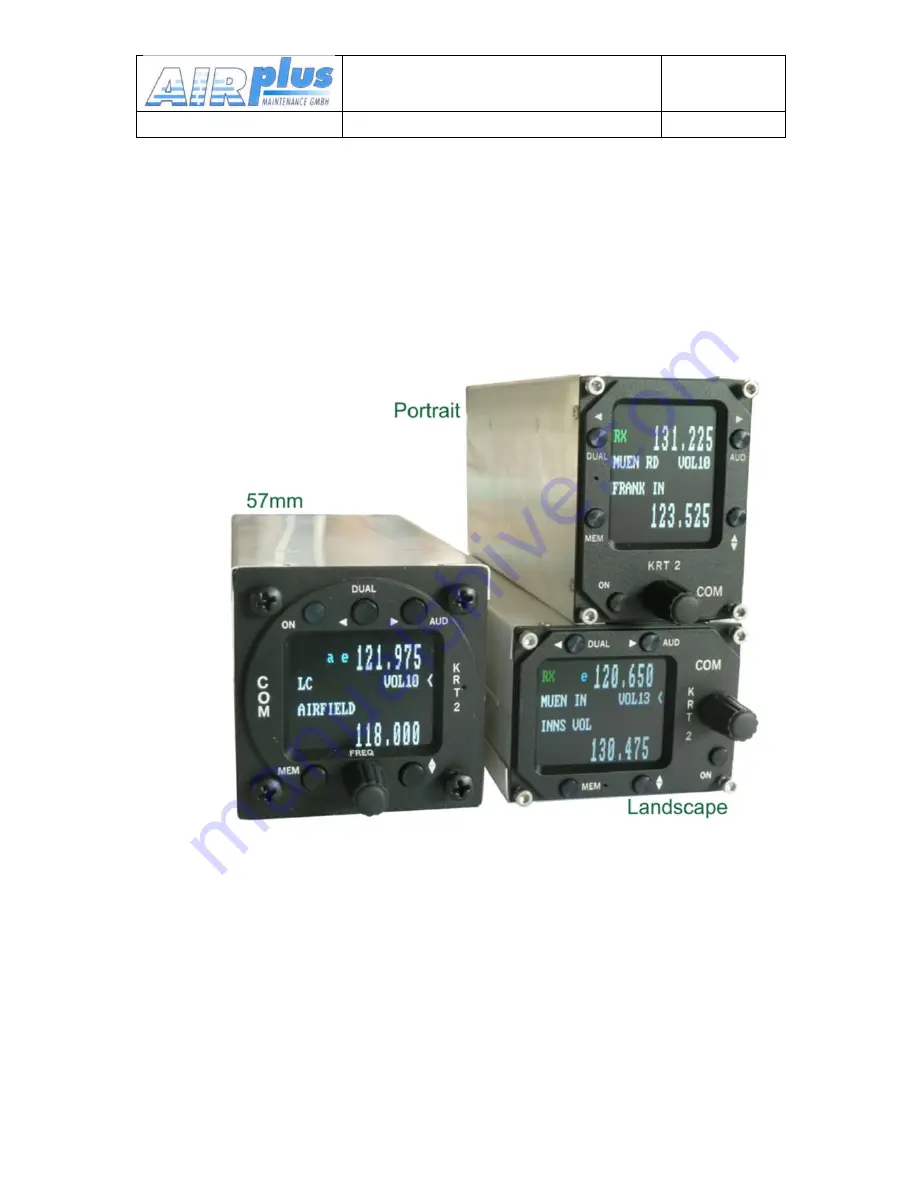
Page 9: ...User Installation manual VHF Communication Transceiver Doc Nr DE 3000 800100e KRT2 Revision 12 2 Jan 2016 9 61 2 CONTROL general 2 1 Control Elements Overview...
Page 10: ...Nr DE 3000 800100e KRT2 Revision 12 2 Jan 2016 10 61 All functions and performances between the normal size unit 57mm round and the Portrait format Mini are identical The only difference to the Mini...
Page 11: ...gramming the station identifier MEM FAVORITES 1 Frequency and identifier selection from the favorites list 2 Programming of favorites frequency and identifier EXCHANGE Exchange of the Active and Stand...
Page 12: ...r volume level default after a certain time delay When AUD was pressed the corresponding Audio Menu item and setting is displayed DUAL Active frequency AND Standby Frequency are monitored simultaneous...
Page 13: ...tandby frequency station identifier Displayed when frequency and identifier are stored in the favourite list 2 3 Audio Menu levels Displayed Signification Remarks VOL Volume Default level SQ Squelch V...
Page 14: ...Internal error Return the transceiver for maintenance Er_FPA Internal error unit not usable Return the transceiver for maintenance Er_I2C Internal error unit not usable Return the transceiver for mai...
Page 15: ...de can be left by pressing the AUD FREQ or MEMORY button When not in the normal mode and there is no pilot action for more than 10 seconds the unit returns to the normal mode 3 2 ON OFF Switching ON O...
Page 16: ...elected range is highlighted and can be changed with the FREQ button Frequency ranges are 1xx nnn 1nn xnn 1nn nxx Press the FREQ button once or several times until the desired frequency range is highl...
Page 17: ...hanges the Active and Standby frequencies The selection procedure can be terminated with either the AUD or FREQ buttons Without pressing any of these buttons the unit will return to its normal operati...
Page 18: ...cters To change frequency just press the FREQ button and follow the normal direct input procedure to edit the frequency To quite the frequency input press the MEMORY button again in order to go to the...
Page 19: ...operating mode When the MEMORY button is pressed at the time when RUN nn is displayed the sorting procedure is terminated The favourite list is then sorted partially only and the transceiver resumes i...
Page 20: ...for more than 10 seconds will result in the VOLnn display Audio Menu items can be accessed in the following order by repeatedly pressing the AUD button VOL default SQ VOX TXm INT EXT DIM SIT MIC Audi...
Page 21: ...nables the turning knob to change the voice level which triggers the intercom The intercom voice trigger level must be set to such a value which prevents that normal cockpit noise from being heard in...
Page 22: ...TX1 TX2 On transmission the PTT L R related microphone will be the only one activated TXm Left Right Both 3 4 6 INT Intercom Volume Pressing the AUD button four times enables the turning knob to set...
Page 23: ...3 4 8 DIM Display Brightness Pressing the AUD button six times enables the turning knob to set the display brightness Display lighting current drain at maximum brightness is 40mA DIMnn Range 01 16 3 4...
Page 24: ...ut channels can be configured individually which enables different microphone types to be used A maximum of two microphones of same type may be connected to each microphone input channel see chapter 5...
Page 25: ...phones often used in gliders Those levels are valid for the left L input only 10 is used for non amplified Electret microphones with a 8 volt supply voltage 11 is for dynamic microphones only For high...
Page 26: ...cognized the presented values will be set The present recognized type will be updated Mic dyn std only if the microphone setup is re entered The MIC submenu is terminated by pressing the AUD button Ad...
Page 27: ...nsceiver KRT2 contains only one receiver DUAL watch is achieved by alternating between the Active and Standby frequencies The DUAL button activates and deactivates the dual watch function Deactivation...
Page 28: ...ve frequency every 2 seconds for 0 3 seconds When reception is detected on the Active frequency the receiver stays on the Active frequency The pointer next to the DUAL display indicates on which frequ...
Page 29: ...gliders when no earphones are in use In order to avoid the blocking of the frequency by unintentional long transmissions stuck microphone the transmitter is switched off after two minutes and the dis...
Page 30: ...is just one PTT possible both the PTT L and PTT R must be tired together see chapter 3 4 5 3 6 2 Self test monitor Operating in the background continuously there is a back ground test system The field...
Page 31: ...dsets are generally not worn and thus no side tone is heard it is very helpful to see if the microphone is working The KRT 2 solves this problem At left lower side there is a modulation indicator that...
Page 32: ...hen resetting is completed DONE is displayed Resetting to the factory settings will not change any data in the favourite list memory 3 8 SET UP Menu During power up the MEMORY buttons must be pressed...
Page 33: ...tarts after the button has been pressed again This procedure may last a few minutes during which time ERASING is displayed All INFO frequencies and identifiers that were stored on delivery are lost an...
Page 34: ...ansmission error R_ChkS Checksum error R_Cmd Unknown command R_Char Data error R_Freq Wrong Frequency The error message disappears when a valid command or a new frequency has been input latest however...
Page 35: ...ss of aircraft must determine that the aircraft installation conditions are within the ETSO TSO standards ETSO TSO articles must have separate approval for installation in an aircraft The article may...
Page 36: ...agram refer to chapter 5 9 Wiring 5 3 Telecommunication Data The following data may be required for the radio station licence Manufacturer AIRplus Maintenance GmbH Type KRT2 EASA Number P N 100 90001...
Page 37: ...stalling the unit in the vicinity of heat sources Sufficient air circulation is required There must be sufficient space for cables and connectors Avoid sharp bends and wiring close to control cables C...
Page 38: ...ply voltage of 8V at 330 is provided Elementary Electret microphones can also be connected They have considerably lower signal levels and therefore require an 8V supply voltage The microphone input ch...
Page 39: ...ether L is the master Because the 8V supply voltage is switched off when dynamic microphones are used during glider flight the second co pilot headset microphone is disabled A maximum of two microphon...
Page 40: ...e connected to ground in order to avoid noise PIN5 must be connected to Battery minus GND 5 7 5 Speaker Connection The high output power for the speaker requires a differential interconnection This do...
Page 41: ...to a level 3 to 10 so that indication is just exceeding of the maximum Leave the menu in position L not AUTO 5 8 2 For motor gliders dual seaters For change mode motoring headset gliding dynamic micro...
Page 42: ...n 2016 42 61 5 9 Wiring 5 9 1 Wire Gauges Supply lines Power GND AWG18 0 83 mm Control lines AWG22 0 38 mm All wires must be aviation certified 5 9 2 Connector Pin Configuration If manual intercom is...
Page 43: ...User Installation manual VHF Communication Transceiver Doc Nr DE 3000 800100e KRT2 Revision 12 2 Jan 2016 43 61 Microphone Setup set L R as required for headset leave not in AUTO...
Page 44: ...User Installation manual VHF Communication Transceiver Doc Nr DE 3000 800100e KRT2 Revision 12 2 Jan 2016 44 61 5 9 3 2Glider two place connection Microphone Setup leave in L 11 not AUTO...
Page 45: ...User Installation manual VHF Communication Transceiver Doc Nr DE 3000 800100e KRT2 Revision 12 2 Jan 2016 45 61 5 9 3 3Glider single Microphone Setup leave with L 11 for dynamic not AUTO...
Page 46: ...Installation manual VHF Communication Transceiver Doc Nr DE 3000 800100e KRT2 Revision 12 2 Jan 2016 46 61 5 9 3 4Motor glider single Microphone Setup set L R as required for headset leave not in AUTO...
Page 47: ...Installation manual VHF Communication Transceiver Doc Nr DE 3000 800100e KRT2 Revision 12 2 Jan 2016 47 61 5 9 3 5Motor glider dual Dynamic Mikrophon Microphone Setup R for headsets leave menu in AUTO...
Page 48: ...User Installation manual VHF Communication Transceiver Doc Nr DE 3000 800100e KRT2 Revision 12 2 Jan 2016 48 61 Electret Mikrophon Microphone Setup leave L 3 9 in case of dynamic 11 R 3 not AUTO mode...
Page 49: ...h the microphone ground The cleanest GND is the case of the radio Put the battery GND to the case and pin 1 and the microphone GND to the pin 9 only 5 9 5 Connection support In order to connect shield...
Page 50: ...have installed a metal sheet foil or mesh of at least 80 80 cm inside the fuselage as electric counterweight In order to avoid interference the distance between a COM an NAV antenna or between a COM a...
Page 51: ...ckpit noise or there are uncompensated microphones VOX should be activated with VOX 01 permanently and enable disable by a manual intercom switch The manual intercom operation is possible with one or...
Page 52: ...lane systems is required to certify that the new wiring is not causing any malfunction The standing wave ratio SWR must be less than 3 1 A test flight is recommended to verify proper transceiver opera...
Page 53: ...ith the ON button The following display will appear The start display shows device type and the software number It then changes into the normal operating mode Direct Input 5 14 Accessories Suitable ac...
Page 54: ...User Installation manual VHF Communication Transceiver Doc Nr DE 3000 800100e KRT2 Revision 12 2 Jan 2016 54 61 5 15 Drawings 5 15 1 Dimensions...
Page 55: ...User Installation manual VHF Communication Transceiver Doc Nr DE 3000 800100e KRT2 Revision 12 2 Jan 2016 55 61 5 15 2 Installation Directions Panel Cut out...
Page 56: ...icing tasks are required on the KRT 2 VHF unit 6 2 Repair Only exchange and flat repair of the equipment is permitted In case of equipment failure the unit must be sent to the manufacturer Refer to se...
Page 57: ...equency MHz Cannel Spacing kHz Displayed channel 8 33 25 kHz Mode Displayed Channel 25 kHz Mode 118 0000 25 118 000 118 000 118 0000 8 33 118 005 118 0083 8 33 118 010 118 0166 8 33 118 015 118 0250 2...
Page 58: ...62mm Width 62 mm Depth 146mm plus rear panel plugs 60mm Dimensions Portrait Height 64mm Width 46 mm Depth 150mm plus rear panel plugs 60mm Dimensions Landscape Height 46mm Width 64 mm Depth 150mm plu...
Page 59: ...9 VDC to 33VDC test 13 8VDC Transmitter 2 0 A typ Receiver 0 13 A Illumination 0 01A to 0 07A Audio Power amp Up to 1A emergency operation 9 VDC Power Consumption Standby 1 6W Transmit 30 W Frequency...
Page 60: ...DULATION 1kHz at m 70 1kHz DUTY CYCLE 2 minutes on 4 minutes off automatic turn off after 2 minutes continuous transmitter operation RECEIVER SENSITIVITY 105 dBm 6 dB S N N m 30 1 kHz BANDWIDTH 25 KHZ...
Page 61: ...User Installation manual VHF Communication Transceiver Doc Nr DE 3000 800100e KRT2 Revision 12 2 Jan 2016 61 61...