R410A 17.5 SEER Inverter Split System Technical Manual
9. Troubleshooting
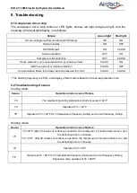
9.1 Compressor driver chip
The compressor driver chip controls 2 LED lights, namely red light and green light, and the
meaning of the fault light display is as follows
:
* The flashing frequency is 2.5Hz, and display of fault code is based on the actual protection time.
9.2 Troubleshooting of sensor
Cooling mode:
Sensor
Operation mode in case of failure
T3
The maximum operating temperature shall not exceed 140
℉
T4
Operate at T4 = 122°F
TP
Operate at T4 = 122°F for T4 temperature frequency limiting and current frequency limiting
Heating mode:
Sensor
Operation mode in case of failure
T3
T4 <45°F: After 40 minutes of continuous operation, the compressor is forced to defrost once, and
the defrosting time is 3 minutes.
T4 >=45°F: After 90 minutes of continuous operation, the compressor is forced to defrost once, and
the defrosting time is 2 minutes.
T4
Operate at T4 = 59°F
TP
Operate at T4 =
59°F
for T4 temperature frequency limiting and current frequency limiting
Expansion valve operates at Tp = 266
°F
Failure
Green light
Red light
DC bus voltage over/low protection (MCE failure)
ON
ON
Normal standby
ON
OFF
EEPROM fault
ON
FLASH
Normal operation
OFF
ON
Compressor stall protection
OFF
FLASH
Phase protection, zero speed protection, synchronous fault
FLASH
ON
IGBT overcurrent or module protection
FLASH
OFF
Communication failure (host data cannot be received for 1min)
FLASH
FLASH
Summary of Contents for ACTH2418VG1-D
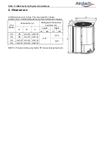
Page 1: ...R410A Inverter Split System 17 5 SEER Technical Manual January 2021 Version A TM 18SS 01...
Page 4: ...R410A 17 5 SEER Inverter Split System Technical Manual 1 Nomenclature 1 1 Indoor unit...
Page 5: ...R410A 17 5 SEER Inverter Split System Technical Manual 1 2 Outdoor unit...
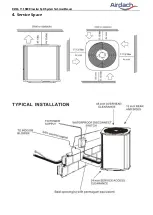
Page 22: ...R410A 17 5 SEER Inverter Split System Technical Manual 4 Service Space...


