


8
MN-751
WirelessONE
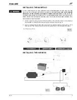
1. Connect electrical connector to manifold (B).
a. Push down till fully seated.
b. Push red secondary lock down.
2. Connect compressor to harness.
a. Cut off terminal on compressor red wire.
b. Strip 1/4” insulation off compressor red wire.
c. Crimp on weather proof blue butt splice (L) to compressor red wire.
d. Crimp on weather proof blue butt splice (L) to harness wire pink wire AL007
(RD/WE-12GA).
e. Heat butt splice to seal connection.
f. Connect the compressor ground wire ring terminal and the relay to the vehicle
ground (fig. 3).
• Using one of the self tapping screws for the compressor you can attach
all the components to the vehicle frame ground.
g. Connect the black wire “Ground to Battery” to the negative battery terminal.
3. Connect the AL004 circuit to the vehicle ignition.
a. Route the AL004 (RD-10GA) wire to a 15A ignition source (G).
• Cut off the excess wire length if all is not needed.
b. Strip off 1/4” insulation off both sides of the inline fuse holder (N) and the AL004
(RD-10GA) wire.
c. Crimp on the weather proof yellow butt splice (M) to AL004 (RD-10GA) wire.
d. Crimp on the weather proof yellow butt splice (M) to one side of the inline fuse
holder (O).
• Heat butt splice to seal connection.
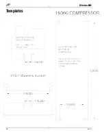
e. Select the appropriate type of fuse tap in terminal for your application (fig. 6).
f. Crimp on the correct terminal that mates with the appropriate type of fuse tap
in terminal for your application.
g. Connect the terminal to the inline fuse holder (N).
h. Install fuse (G).
ATTACHING THE AIR LINES
Manifold to Compressor:
1. Cut a section of the ¼” DOT air line (D) provided to go from manifold to compressor.
2.
Press air line (D) over barb fitting of compressor (C).
3. Insert into “C” port of manifold (B).
Manifold to “T-Fitting”:
1. Cut a section of the 1/4” DOT air line (D) provided to go from manifold (B) to
“T- Fitting” (F).
2.
Press air line (D) into the ”1” fitting of manifold (B).
3.
Press other side of air line (D) into “T” fitting (F).
Adapter #1
Adapter #2
*
Adapter
Fuse
*
Uses 3/16 (smaller) Female Push On Connector
fig. 6