9
MN-282
RideControl
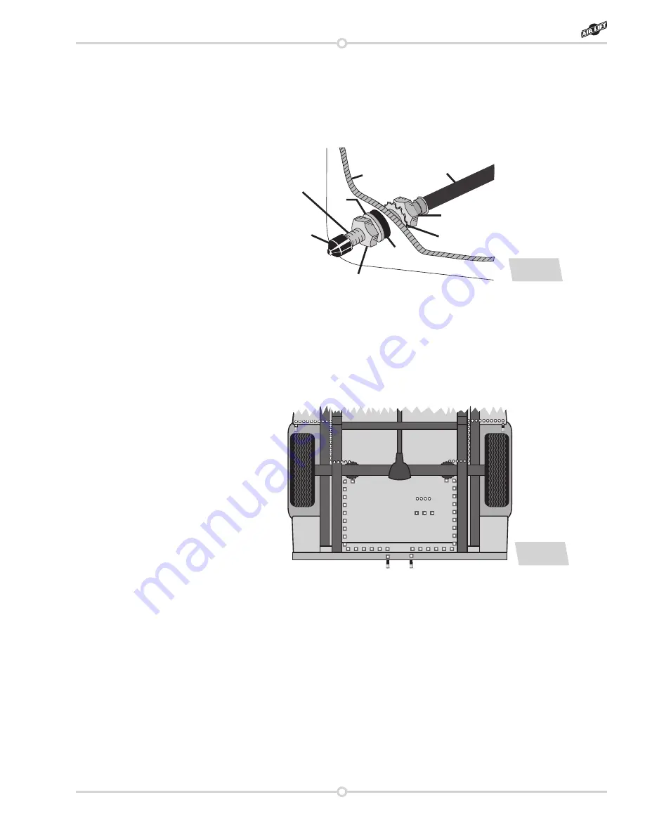
2 . Drill two 5/16” holes to install the inflation valves .
3 . Cut the air line assembly in two equal lengths .
4 . Place a 5/16” nut and star washer on the air valve . Leave enough of the inflation valve
in front of the nut to extend through the hole and have room for the rubber washer, flat
washer, and 5/16” nut and cap . There should be enough valve exposed after installation
– approximately 1/2” – to easily apply a pressure gauge or an air chuck . (Fig . 8)
Air line to
air spring
Star
washer
Vehicle body
or bumper
Hex nut
Hex nut
Rubber
washer
Flat
washer
Valve
Cap
Schrader
valve
fig. 8
5 . Push the inflation valve through the hole and use the rubber washer, flat washer and
another 5/16” nut to secure it in place . Tighten the nuts to secure the assembly .
6 . Route the air line along the frame to the air fitting on the air spring (Fig . 9) . Keep
AT LEAST 6” of clearance between the air line and heat sources, such as the exhaust
pipes, muffler, or catalytic converter . Avoid sharp bends and edges . Use plastic tie straps
to secure the air line to fixed points along the chassis . Be sure that the tie straps are tight,
but do not pinch the air line . Leave at least 2” of slack to allow for any movement that
might pull on the air line .
7 . Cut off the air line, leaving approximately 12” of extra air line . A clean square cut will
prevent leaks . Insert the air line into the air fitting . This is a push-to-connect fitting .
Simply push the air line into the 90° swivel fitting until it bottoms out (9/16” of air line
should be in the fitting) .
fig. 9
Option 1:
Option 2:
ALIGNING THE AIR SPRING
1 .
VERY IMPORTANT
– The upper and lower brackets are slotted in order to assist in
aligning the air spring correctly between the brackets . With the top and bottom still
loose, inflate the air springs to approximately 10 PSI . Tap the air spring inboard or
outboard to achieve proper alignment . There should be a symmetrical cushion of air
around the base of the air spring when correctly positioned . Once the air springs are
aligned correctly, torque the upper mounting bolt to a maximum of 4 lb .-ft . (5Nm) and
the lower mounting bolt to a maximum of 20 lb .-ft . (27Nm)
2 . Install the wheels and torque to manufacturers specifications, remove the safety
stands and lower the vehicle .
Summary of Contents for RideControl 59516
Page 2: ......
Page 17: ...15 MN 282 RideControl Notes...


