


6. Line up sleeve perpendicular to upper and lower bracket and
tighten upper nut to 15 ft-lbs. Install air fitting (this fitting is
precoated with thread sealant) finger tight plus two turns.
Use a
7/16” open end wrench being careful to tighten on
the metal hex nut only. DO NOT OVER TIGHTEN.
Orient the fitting so that it faces in the direction of your intended
air line route.
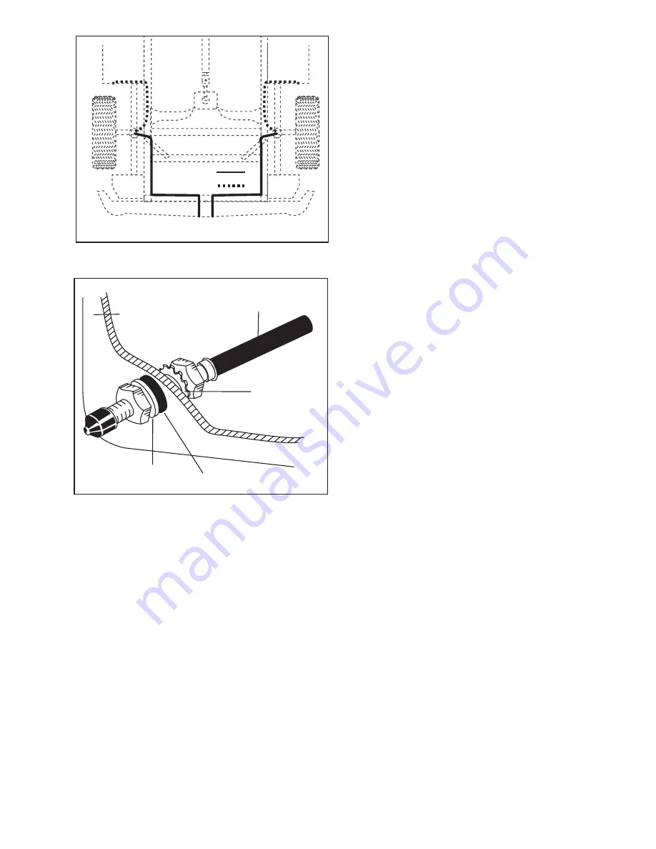
7. Select a location for the inflation valves in the rear bumper area or
rocker panel flange insuring that each valve will be protected and
accessible with an air hose (Figure 6).
8. Use a standard tube cutter, a razor blade, or very sharp knife to
cut the air line. A clean square cut will ensure against leaks. Cut
the air line in two equal lengths, not more than 96” long. Drill 5/16”
hole for inflation valve and mount as illustrated. Rubber washer
on outside is for weather seal (Figure 6).
9. Route air line along frame to desired inflation valve location
(Figure 6). Attach air line to chassis with the provided plastic
straps.
TO PREVENT AIR LINE FROM MELTING, KEEP IT AT
LEAST TWELVE INCHES FROM EXHAUST SYSTEM.
10. Cut off excess air line squarely. Install the air line into the fitting.
This is a self locking fitting. Push and slightly turn the cut end of
the air line into the fitting as far as it will go. You will hear/feel
a definite “click” when the air line is seated. The air line is now
installed. Air line should go in approximately 3/4 inch.
11. Repeat process for right side.
12.
VERY IMPORTANT
- With the bottom still loose, inflate the
sleeve to approximately 10 p.s.i. By using the slotted adjustments,
align the sleeve so that there is a symmetrical cushion of air
around the lower base of the sleeve to prevent side load wear.
Tighten the lower sleeve mounting bolt to10 ft-lbs.
13. Inflate to 30 p.s.i. Check all fittings and valve core with a soapy
water solution for leaks. Check once again to be sure you have
proper clearance around the sleeve. When the sleeve is inflated
there must be 1/2” of clearance all around the sleeve.
14. Recheck air pressure after 24 hours. A 2-4 p.s.i. loss after initial
installation is normal. If pressure has dropped more than 5 lbs.
re-test for leaks with soapy water solution. Please read and follow
the Maintenance and Operating tips. (Check to see that the
sleeve rolls back down over the bottom piston after the vehicle is
lowered.)
Option 1
Option 2
Air Line to
Bellows
Star
Washer
Vehicle body
or bumper
Rubber Washer
Flat Washer
FIGURE 5
FIGURE 6
3


