background image

LoadLifter 5000 Series

MN-1085

7

LEFT

fig. D.11

RIGHT

O

O

Ensure 
fitting is 
less than 
7/8" in 
height

fig. D.15

T

U

V

fig. D.13

fig. D.14

ASSEMBLING THE AIR SPRINGS

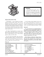
1.  Place a 3/8"-16 x 3"carriage bolt (O) through the inner most square hole on the rear 

side of each lower bracket (B) (Fig. D.11).

The radiused (rounded) edge of the roll plate (F) will be toward the air spring so that the air 
spring is seated inside the roll plate.

2.  Install a lower bracket (B) and roll plate (F) on each air spring (E) using two 3/8"-24 

x 3/4" flat head socket cap screws (S) through the innermost mounting holes (Fig. 
D.12). Torque the flathead screws to no more than 20 lb.-ft. (27Nm) (Fig. D.12).

3.  Install the 90 degree swivel elbow fitting (R) into the top of each air spring finger tight. 

Tighten the swivel fittings an additional one and a half turns (Fig. D.12). 

4.  Attach the upper roll plates (F) and upper brackets (A) to the air springs (E) using two 

3/8"-24 x 7/8" bolts (T), two 3/8" lock washers (U) and two 3/8" flat washers (V) for 
each assembly (Fig. D.13). Torque bolts to no more than 20 lb.-ft. (27Nm). These 
brackets are not left or right hand specific (Fig. D.14). 

5.  With the bracket installed, ensure the swivel fitting is less than 7/8" in height, and if 

not, tighten the fitting until this height is achieved (Fig. D.15).

B

B

R

fig. D.12

O

F

E

NOTE

Summary of Contents for LoadLifter 5000 Series

Page 1: ...d these instructions completely before proceeding with installation Installation Guide MN 1085 011810 ERN 9073 Failure to read these instructions can result in an incorrect installation GM Silverado S...

Page 2: ...ylon air lines LoadLifter 5000 Ultimate Plus Stainless steel roll plates braided stainless steel air lines stainless steel air spring mounting hardware Air Lift offers two Ultimate Plus upgrade kits 5...

Page 3: ...Started 5 Assembling the Air Springs 7 Installing the Air Springs 8 Attaching the Upper Brackets 8 E Installing the Air Lines 10 Installing Nylon Air Lines 10 Installing Braided Stainless Steel Air L...

Page 4: ...O B D N N C S F V U N T R E P P fig A 1 Optional hardware for vehicles equipped with fifth wheel hitches that have frame side plates see page 9 for details NOTE If the truck has fifth wheel hitch brac...

Page 5: ...lbow fitting 2 S 17215 3 8 24 x 3 4 Flat head socket cap screw 4 T 17203 3 8 24 x 7 8 Hex head cap screw 4 U 18427 3 8 Split Lock washer 4 V 18444 3 8 Flat washer 4 Y 21230 Valve cap 2 Z 21233 5 16 32...

Page 6: ...rming any maintenance service or repair NOTATION EXPLANATION Hazard notations appear in various locations in this publication Information which is highlighted by one of these notations must be observe...

Page 7: ...ropped away from the frame This will need to be done for the air spring assembly to be put into position between the axles and frame Fig D 1 2 Remove the factory bolts that hold the upper brake line b...

Page 8: ...side of the axle Fig D 6 5 Remove the brake line bracket attached to the axle under the leaf spring on both sides of the vehicle Set bolt aside for reinstallation 6 Attach the brake line tab bracket...

Page 9: ...ugh the innermost mounting holes Fig D 12 Torque the flathead screws to no more than 20 lb ft 27Nm Fig D 12 3 Install the 90 degree swivel elbow fitting R into the top of each air spring finger tight...

Page 10: ...d clamp bracket C with the hole on the front of the lower bracket B Fig D 16 3 Insert two carriage bolts O on the front and rear square holes of the lower bracket B both sides Figs D 16 D 17 4 Thread...

Page 11: ...16 lb ft 27Nm For trucks that have fifth wheel hitch brackets alongside the frame rail 1 There are holes in the middle of the bracket just forward and behind the jounce bumper mounting cups on the up...

Page 12: ...on Fig E 3 Good cut Bad cut A Inside fuel tank filler door B Inside rear wheel wells C License plate or rear bumper area For LoadLifter 5000 Ultimate Plus kits the recommended location for the Schrade...

Page 13: ...en location 3 Coil and secure any excess air line in an area where it will not be susceptible to damage The braided stainless steel air line cannot be trimmed Hex nuts Star washer Rubber washer Air Li...

Page 14: ...view 1 The images show the finished installation of both sides Figs F 1 F 2 F 3 F 4 Finished installation images show the LoadLifter 5000 Ultimate Plus kit installed F Finished Installation fig F 1 f...

Page 15: ...the vehicle is road tested Heat test Be sure there is sufficient clearance from heat sources at least 6 152mm for air springs and air lines If a heat shield was included in the kit install it If there...

Page 16: ...322 2144 JJC 1018 Thank you for purchasing Air Lift Products the Authorized Installer s choice Air Lift Company 2727 Snow Road Lansing MI 48917 or P O Box 80167 Lansing MI 48908 0167 Printed in the U...

Reviews: