64
SB405-PV User Manual
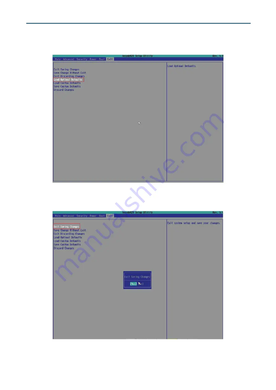
Chapter 4 BIOS Configuration Settings
Load Optimal Default Setting.
Save the setting and exit the BIOS setup utility.
Page 1: ...UM_SB405 PV_v1 4_061419 SB405 PV Storage Barebone User s Manual...
Page 2: ...allation BTO 13 2 2 System Memory 14 2 2 1 Dual Processor 14 2 2 2 Recommended Dimm Installation Order 15 2 2 3 Single Processor with Raid Card Function BTO 17 2 2 4 Populate DIMMs with the Single Pro...
Page 3: ...erboard Content List 41 3 3 Motherboard Layout 42 3 4 Internal Connectors Jumpers 43 3 5 System LED Indicator 48 3 5 1 Front Panel LED 48 3 5 2 Rear I350 LAN LEDs 48 3 5 3 Rear PCH LAN LEDs 49 3 5 4 R...
Page 4: ...76 4 5 1 Security 76 4 6 Power 77 4 6 1 Power 77 4 7 Boot 78 4 7 1 Boot 78 4 8 Exit 79 4 8 1 Exit 79 Chapter 5 BMC Configuration Settings 80 5 1 Method 1 Use the BIOS Setup 80 5 2 Method 2 Use a Dos...
Page 5: ...ate Version Update Content August 2018 1 User s Manual release to public December 2018 1 1 1 Update cover 2 Update Motherboard Setting Febuary 2019 1 2 1 Update Datasheet March 2019 1 3 Update Slide R...
Page 6: ...Copyright 2018 AIC Inc All Rights Reserved This document contains proprietary information about AIC products and is not to be disclosed or used except in accordance with applicable agreements...
Page 7: ...le for compliance could void your authority to operate the equipment Disclaimer AIC shall not be liable for technical or editorial errors or omissions contained herein The information provided is prov...
Page 8: ...efully mount the equipment into the rack in such manner that it won t be hazardous due to uneven mechanical loading This equipment is to be installed for operation in an environment with maximum ambie...
Page 9: ...Do not use liquid or detergent for cleaning The use of a moisture sheet or cloth is recommended for cleaning Module and drive bays must not be empty They must have a dummy cover CAUTION The equipment...
Page 10: ...Settings This chapter provides descriptions for the hardware including multifarious connectors jumpers and LED descriptions These descriptions assist users to configure different settings and functio...
Page 11: ...indicate that the contents of the carton are damaged If any damage is found do not remove the components contact the dealer where the subsystem was purchased for further instructions Before continuing...
Page 12: ...SAS HD 2 x SATA 6 0 Gb s by 2 x SATA 7 pin 5 x SATA 6 0 Gb s by Max I O BMC Aspeed AST2500 Advanced PCIe Graphics Remote Management Processor Baseboard Management Controller Intelligent Platform Inter...
Page 13: ...ter bandwidth and utilization In addition to the noteworthy features of the barebone SB405 PV provides immediate and efficient management with Onboard Baseboard Management Controller and greater I O e...
Page 14: ...User Manual Front Panel SB405 PV offers 2 system buttons Power Reset and 3 LED indicators System Power System Hard Drive Disk Activity Service ID Power Button System Power LED System HDD Activity LED...
Page 15: ...dedicated to BMC management x 1 USB connectors and headers USB 3 0 Type A connectors x 1 USB internal pin header to support two USB 3 0 x 1 USB internal pin header to support two USB 2 0 x 1 1 VGA por...
Page 16: ...6 Chapter 1 Product Features SB405 PV User Manual Major Components SB405 PV offers 3 5 hotswap drive bays x 102 and 2 5 hotswap drive bays x 2...
Page 17: ...ver board includes two processor sockets LGA3647 that provides one or two processors of the Intel Xeon Processor Scalable Family and supports a Thermal Design Power TDP of up to 165W on selected model...
Page 18: ...with a loading mechanism that is designed to secure the Processor Heat Sink Module PHM to the server board as shown below CAUTION Previous generations of the Intel Xeon Processors and heatsinks are no...
Page 19: ...Sink Module The PHM refers to the sub assembly where the heat sink and processor are clipped together onto the server board prior to installation The PHM consists of the components shown below Proces...
Page 20: ...eated over the processor socket assembly the four heat sink torque screws must be tightened in order as shown below Processor Heat Sink Top View with Screw Tightening Order CAUTION Failure to tighten...
Page 21: ...PU0 and CPU1 and align the screws on the heatsink with the screw holes on the motherboard CAUTION Avoid moving the heatsink after it has contacted the top of the CPU Too much movement could disturb th...
Page 22: ...12 Chapter 2 Hardware Setup SB405 PV User Manual 2 1 5 Heatsink for Single Processor only with RAID card Function BTO Position the heatsink on top of CPU 0...
Page 23: ...rdware Setup SB405 PV User Manual 2 1 6 Riser Card Installation BTO Step 1 Secure the riser card onto the motherboard with screws Step 2 Secure the top cover that covers the fan with screws to complet...
Page 24: ...ECC DRAM Load Reduced DIMM LRDIMM NOTE In Pavo Case the 16 lanes from CPU 0 and the 8 lanes from CPU 1 are routed to PCIe slot1 The lanes from the CPU 1 are routed to the PCIe slot 3 and 4 CPU0 CPU0...
Page 25: ...CPU1 JDIMMD2 JDIMMK2 JDIMML JDIMMM JDIMMK1 JDIMMD1 JDIMME JDIMMF JDIMMC JDIMMB JDIMMA1 JDIMMA2 JDIMMJ JDIMMH JDIMMG1 JDIMMG2 6 DIMMs CPU0 CPU1 JDIMM_C JDIMM_J JDIMM_A1 JDIMM_G1 JDIMM_F JDIMM_M CPU0 C...
Page 26: ...JDIMML JDIMMM JDIMMK1 JDIMMD1 JDIMME JDIMMF JDIMMC JDIMMB JDIMMA1 JDIMMA2 JDIMMJ JDIMMH JDIMMG1 JDIMMG2 JDIMM_C JDIMM_B JDIMM_A1 JDIMM_D1 JDIMM_E JDIMM_F JDIMM_J JDIMM_H JDIMM_G1 JDIMM_K1 JDIMM_L JDIM...
Page 27: ...ter 2 Hardware Setup SB405 PV User Manual 2 2 3 Single Processor with Raid Card Function BTO You can only use CPU0 with the single processor CPU0 CPU0 DIMMC DIMMB DIMMA1 DIMMA2 DIMM_D2 DIMM_D1 DIMM_E...
Page 28: ...umbers DIMM ARRANGMENT 1 DIMMs CPU0 JDIMM_B0 JDIMMC1 JDIMMC0 JDIMMD1 JDIMMD0 JDIMMB0 JDIMMB1 JDIMMA0 JDIMMA1 CPU0 2 DIMMs CPU0 JDIMM_B0 JDIMM_A0 JDIMMC1 JDIMMC0 JDIMMD1 JDIMMD0 JDIMMB0 JDIMMB1 JDIMMA0...
Page 29: ...JDIMMD0 JDIMMB0 JDIMMB1 JDIMMA0 JDIMMA1 CPU0 6 DIMMs JDIMM_B0 JDIMM_B1 JDIMM_C0 JDIMM_D0 JDIMM_A0 JDIMM_A1 JDIMMC1 JDIMMC0 JDIMMD1 JDIMMD0 JDIMMB0 JDIMMB1 JDIMMA0 JDIMMA1 CPU0 JDIMM_B0 JDIMM_B1 JDIMM_...
Page 30: ...he dimm socket by pressing the retaining clips outward Step 2 Insert the memory module into the slot Make sure that the dimm notch is accurately positioned Step 3 Close the retaining clips to complete...
Page 31: ...21 Chapter 2 Hardware Setup SB405 PV User Manual The server consists of four covers cover A B C D This information is provided for professional technicians only 2 3 Top Cover...
Page 32: ...dware Setup SB405 PV User Manual 2 3 1 Removing the Top Cover A B Push the release button on both sides of the top cover Lift upward to remove the cover This information is provided for professional t...
Page 33: ...dware Setup SB405 PV User Manual 2 3 2 Removing the Top Cover C D Push the release button on both sides of the top cover Lift upward to remove the cover This information is provided for professional t...
Page 34: ...Hardware Setup SB405 PV User Manual 2 4 1 Removing the Motherboard Loosen the thumb screw to remove the motherboard from the chassis This information is provided for professional technicians only 2 4...
Page 35: ...User Manual 2 5 1 Removing the Power Supply Unit Push the latch upward and hold the tray handle Pull the tray handle on the power supply module This information is provided for professional technicia...
Page 36: ...re Setup SB405 PV User Manual 2 6 1 Installing the Fan Push the fan module into the chassis Secure the thumb screws x 2 pcs on the fan module This information is provided for professional technicians...
Page 37: ...ess tray Align the HDD with the tray by placing it against each other Insert the HDD into the tool less tray in the suggested order above Make certain to attach the side of the tray with the larger di...
Page 38: ...n 2 7 2 Removing the HDD from the tool tray Pull the sides of the tray to remove the HDD Make certain to pull the tray with smaller dimples first away from the HDD and the larger dimples last for easi...
Page 39: ...Installing Removing the HDD Tray Inser the HDD tray into the chassis Check if the drive tray is correctly secured in place where the front edge aligns with the edge of the bay 2 7 3 1 The 2 5 Tray Mod...
Page 40: ...30 Chapter 2 Hardware Setup SB405 PV User Manual 2 7 3 2 Installing the 2 5 HDD tray into the chassis Press downward on the tray lever Insert the 2 5 HDD into the chassis until it clicks...
Page 41: ...B405 PV User Manual 2 7 3 3 Installing the 3 5 HDD tray into the chassis Adjust and press downward on the tray lever Insert the tray into the chassis until it clicks This information is provided for p...
Page 42: ...le and secure the screws x 8 pcs 1 bracket with 2 screws each Repeat step 1 and step 2 to install the second backplane 2 8 2 Removing the HDD Backplane Remove the HDD disk trays from the chassis Remov...
Page 43: ...33 Chapter 2 Hardware Setup SB405 PV User Manual This information is provided for professional technicians only...
Page 44: ...p SB405 PV User Manual 2 9 1 Installing the Cable Cover Position the cable cover onto the chassis Secure the thumb screw x 1 pc on the cable cover This information is provided for professional technic...
Page 45: ...p SB405 PV User Manual 2 10 1 Installing the Bridge Board Insert the bridge into the chassis Secure the screws x 2 pcs on the side of the bridge This information is provided for professional technicia...
Page 46: ...ual 2 11 1 Installing the Rear Handle Match the locking plate on the handle with the locks on the chassis Pull the handle upward to lock the handle onto the chassis This information is provided for pr...
Page 47: ...d the airduck according to the dotted line on the airduck Slide the airduck under the heatsink and secure the screw x 2 pcs Make certain to match the length of the airduck with the side of the dimm 2...
Page 48: ...ail is hooked onto the rack Align and attach the rear rail braket to the rack by pushing the latch outward Ensure the latch is hooked onto the rack Ensure that the latch on the rail is hooked onto the...
Page 49: ...the inner and middle rail to fully locked position Position the chassis vertically into the rail Ensure the standoffs on the chassis slide into the v slots on the rail bracket Secure the chassis to th...
Page 50: ...40 SB405 PV User Manual Chapter 3 Hardware Settings This section describes the jumpers internal connectors and internal LED settings 3 1 Motherboard Block Diagram Chapter 3 Hardware Settings...
Page 51: ...PCH SSGPIO Header J27 9 Front USB 3 0 Port J16 31 BMC Disable J30 10 Front USB 2 0 Port J49 32 Password Clear J31 11 DIMM Slots J56 J58 J61 J65 J69 J76 33 PECI J44 12 CPU Sockets U55 U78 34 VRM SMB H...
Page 52: ...hapter 3 Hardware Settings 3 3 Motherboard Layout 37 a 3 b 3 a 27 9 18 13 6 8 7 14 28 25 29 30 16 10 44 43 36 5 1 24 26 2 34 9 15 31 32 21 35 42 41 22 40 39 23 38 b 20 4 17 19 a 38 a 11 16 DIMM Socket...
Page 53: ...D VGA_5V AHSYNCO DACBO GND NC DACRO 1 2 15 16 10 2 9 1 DSR RTS CTS RI NC DCD RXD TXD DTR GND 3 4 Internal Connectors Jumpers 13 6 8 7 GND KEY P5V PCH_IO2 PCH_IO1 GND SMB_PCH_SDA ESPI_CS1 PCH_CLKRUN ES...
Page 54: ...AD SGPIO_SATA0_CLOCK 1 3 GND RXD TXD I2C1SDA GND I2C1SCL NC 5 1 1 23 2 24 GND FAN_PWM5 FAN_PWM4 FAN_PWM3 FAN_TACH11 FAN_TACH10 FAN_TACH9 FAN_TACH8 FAN_TACH7 FAN_TACH6 I2CSCL GND GND FAN_PWM2 FAN_PWM1...
Page 55: ...rt J16 18 Intruder Header J47 37 BMC Fan Header J51 11 20 10 1 VDD_USB_P34 USB3_RX_N2 USB3_RX_P2 GND USB3_TX_N2 USB3_TX_P2 GND USB2_N2 USB2_P2 PCH_USB_OC 2 KEY VDD_USB_P34 USB3_RX_N3 USB3_RX_P3 GND US...
Page 56: ..._BTN GND PWR_BTN HD_LED HD_LED PWR_LED KEY PWR_LED LAN2_ACT LAN2_ACT INTRUDER_N I2CCLK I2CSDA LAN1_ACT LAN1_ACT FAULT_LED FAULT_LED UID_LED UID_LED 3 3V_DUAL 1 2 23 24 CHASSIS_1U2N_N BNC_GPIO_EXI N FA...
Page 57: ...M 41 BMC Reset J23 J23 Setting Short BMC Reset Open Normal Default 21 Speaker Header J48 31 BMC Disable J30 J30 Setting Short BMC Disable Open Normal Default 39 BIOS Recovery Mode J37 J37 Setting Shor...
Page 58: ...n Blinking Disk activity is detected Off No disk activity is detected LAN1_TRAFFIC Green Blinking LAN1 activity is detected Off LAN1 is not active LAN2_TRAFFIC Green Blinking LAN2 activity is detected...
Page 59: ...CH LAN LEDs LED5 Green LAN1 activity is detected Off LAN1 is not active LED7 Green LAN1 link is detected Off LAN1 is not linked LED6 Green LAN0 activity is detected Off LAN0 is not linked LED4 Green L...
Page 60: ...ID is not active LED2 On BMC Rack LAN activity is detected Only for Rack Off BMC Rack LAN is not active Only for Rack LED3 On BMC Rack LAN activity is detected Only for Rack Off BMC Rack LAN is not ac...
Page 61: ...r Manual 3 6 1 Placement 24 Bay HDD13 HDD14 HDD15 HDD16 HDD17 HDD18 HDD19 HDD20 HDD21 HDD22 HDD23 HDD24 HDD 1 HDD2 HDD3 HDD4 HDD5 HDD6 HDD7 HDD8 HDD9 HDD10 HDD11 HDD12 U6 Sensor U80 Sensor Expander Ex...
Page 62: ...for debug use JFAN1 JFAN2 Control for Expander JEXP_UART1 JEXP_UART2 DBG_SIRXD GND DBG_SITXD SM_SITXD GND SM_SIRXD 3V3 SLOAD2 SCLOCK2 SLOAD1 SCLOCK1 CPLD SCL 5V SDATAOUT2 GND SDATAOUT1 CPLD SDA GND F...
Page 63: ...n HDD present Blue Blinking HDD Activity is detected 8Hz HDD Locate 0 5Hz Off HDD is not connected or Power is off HDD Fault Status LEDs Red On Set by any of the following bits 1 RQST MISSING 2 RQST F...
Page 64: ...54 SB405 PV User Manual Chapter 3 Hardware Settings 3 6 4 LED Locations 24 Bay SASHD_S1 PHY Link LED SASHD_S2 PHY Link LED LEDA1 to LEDA8 LEDA9 to LEDA16...
Page 65: ...55 Chapter 3 Hardware Settings SB405 PV User Manual HDD Activity LED HDD Fault Status LED Expander Blinking LED Expander HeartLED...
Page 66: ...3 HDD1 HDD2 HDD4 HDD5 HDD6 HDD7 HDD8 HDD9 HDD10 HDD11 HDD12 HDD13 HDD14 HDD15 HDD16 HDD17 HDD18 HDD19 HDD20 HDD21 HDD22 HDD23 HDD24 HDD25 HDD26 HDD27 HDD28 HDD29 HDD30 U11 Sensor U92 Sensor Expander F...
Page 67: ...SCLOCK2 SLOAD1 SCLOCK1 CPLD SCL 5V SDATAOUT2 GND SDATAOUT1 CPLD SDA GND Power Connector JPW2 Front LED Board Control for Display HDD LED Status LED BD1 C Control for Expander JEXP_UART1 6 2 5 1 DEBUG...
Page 68: ...resent Blue Blinking HDD Activity is detected 8Hz HDD Locate 0 5Hz Off HDD is not connected or the Power is off HDD Fault Status LEDs Red On Set by any of the following bits 1 RQST MISSING 2 RQST FAUL...
Page 69: ...59 Chapter 3 Hardware Settings SB405 PV User Manual 3 7 3 LED Locations 30 Bay SASHD_S1 PHY Link LED LEDA1 to LEDA8 HDD Activity LED HDD Fault Status LED...
Page 70: ...60 SB405 PV User Manual Chapter 3 Hardware Settings Expander Blinking LED Expander Heartbeat LED...
Page 71: ...tem off and on NOTE The following pages provide the details of BIOS menu Please be noticed that the BIOS menu are continually changing due to the BIOS updating The BIOS menu provided are the most upda...
Page 72: ...sic system information and date time Advanced Allows configuration of advanced system settings Security Sets passwords and security functions Power Sets the power management parameters Boot Sets boot...
Page 73: ...ation Settings SB405 PV User Manual There will be a message Entering SETUP displayed on the diagnostics screen Identify the BIOS version NOTE For the official released version the last digit of the BI...
Page 74: ...64 SB405 PV User Manual Chapter 4 BIOS Configuration Settings Load Optimal Default Setting Save the setting and exit the BIOS setup utility...
Page 75: ...65 Chapter 4 BIOS Configuration Settings SB405 PV User Manual Main Option Key 4 3 1 Main Option Key Description System time Configures the current time System date Configures the current date 4 3 Main...
Page 76: ...PCIe ARI Enable Disable ARI Forward Enable Disable Spread Spectrum Enable Disable Redfish On Off Enable Disable 4 4 2 Video Configuration Video Configuration Display Mode Plug In First On Board First...
Page 77: ...ncy Select 9 6Gb s 10 4Gb s Auto Use Per Link Setting Link L0p Enable Auto Enable Disable Link L1 Enable Auto Enable Disable Legacy VGA Socket Min 0 Max 3 Legacy VGA Stack Min 0 Max 6 Memory Configura...
Page 78: ...able PCIe ACPI Hot Plug Enable Disable Per Port MC BaseAddress Range Auto Below 4G MC Index Position 12 20 MC Num Group 1 8 32 64 PCI E Completion Timeout Global Disable No Yes Per Port PCI E Global T...
Page 79: ...are PM State Control Hardware P States Disable Native Mode Out of Band Mode Native Mode with No Legacy Support HardwarePM Interrupt Enable Disable EPP Enable Enable Disable EPP profile Performance Bal...
Page 80: ...t Plug Enable Disable Configure as eSATA Enable Disable Mechanical Presence Switch Enable Disable Spin Up Device Enable Disable SATA Device Type Hard Disk Drive Sata State Drive SATA Topology Unknown...
Page 81: ...eSATA Enable Disable Spin Up Device Enable Disable sSATA Device Type Hard Disk Drive Sata State Drive SATA Topology Unknown ISATA Direct Connect Flex M 2 Port 1 Enable Disable Hot Plug Enable Disable...
Page 82: ...ec 1s 3 5s Disable MPL for Uplink x16 MPL for Uplink x8 MPL 128B MPL 256B MPL 512B PCIE Clock Gating Enable Disable PCH DMI ASPM Platform POR ASPM L Disable DMI Link Extended Synch Control Enable Disa...
Page 83: ...Error Reporting Enable Disable PCIe Speed Auto Gen 1 Gen 2 Gen 3 MSI Enable Disable PCIE Lane Topology Unknown x1 x4 Sata Express M 2 Max Payload Size MPL MPL 128B MPL 256B Compl Timeout 40 50ms spec...
Page 84: ...Max 240 ACPI SPMI Table Enable Disable Boot Option Support Enable Disable Set BIOS version to BMC Enable Disable BMC Configuration Watchdog Timer Support Enable Disable Not disable in OS Enable Disabl...
Page 85: ...Rate 1200 2400 4800 9600 19200 38400 57600 115200 Data Bits 7 Bits 8 Bits Parity None Even Odd Stop Bits 1 Bits 2 Bits Flow Control None RTS CTS XON XOFF Information Wait Time 0 Second 2 Seconds 5 Se...
Page 86: ...on Settings Security Option Key 4 5 1 Security Security Current TPM Device Not Detected TPM 1 2 TPM 2 0 TrEE Protocol Version 1 0 1 1 TPM Availability Available Hidden TPM Operation No operation Disab...
Page 87: ...77 Chapter 4 BIOS Configuration Settings SB405 PV User Manual Power Option Key 4 6 1 Power Power Wake on PME Enable Disable 4 6 Power...
Page 88: ...Quiet Boot Enable Disable Network Stack Enable Disable PXE Boot to LAN Enable Disable PXE Boot capability Disable UEFI IPv4 UEFI IPv6 UEFI IPv4 UEFI IPv6 Legacy Add Boot Options First Last Auto ACPI S...
Page 89: ...your changes without exiting the system Exit Discarding Changes Discard your changes when existing the system Load Optimal Defaults Load optimal default items Load Custom Defaults Resets the BIOS sett...
Page 90: ...onfiguration Settings Insert Ethernet LAN cable into the BMC LAN port There are two methods to setup BMC IP 5 1 Method 1 Use the BIOS Setup BIOS SETUP Advanced H2O IPMI configuration BMC Configuration...
Page 91: ...81 SB405 PV User Manual Chapter 5 BMC Configuration Settings Type in the IP address Configure the static IP adress...
Page 92: ...82 Chapter 5 BMC Configuration Settings SB405 PV User Manual Type in the subnet mask address Type in the gateway address...
Page 93: ...anual Chapter 5 BMC Configuration Settings 5 2 Method 2 Use a Dos Tool Syscheck Type in sc lanset Modify the IP setting NOTE Type 1 for selecting Static IP Mode or type 2 for selecting DHCP Mode Type...
Page 94: ...Manual Type in the submask address The IP address below is an example using a default IP setting The IP address is configurable Configure the gateway address to complete the BMC IP setting NOTE Type S...
Page 95: ...r Static by the BIOS utility or the system check Open the browser then type the BMC IP address Use the default user name and password for first time BMC WEB GUI login Field Default UserName admin Pass...
Page 96: ...and Reports page monitors and reports on the status of IPMI event and video Settings The Settings page allows you to configure various basic settings such as date time KMV Mouse Services and ect Remo...
Page 97: ...mands are allowed except for the configuration commands that can change the behavior of the out of hand interfaces Administrator All BMC commands are allowed No access Login access denied Notification...
Page 98: ...status of adevice 5 4 4 Sensor The Sensor Readings page displays all the sensor related information 5 4 5 FRU Information The FRU Information page displays Basic Information Chassis Information Board...
Page 99: ...C Configuration Settings 5 4 6 Logs and Report The System Inventory page displays IPMI Event Log and Video Log Click Logs and Reports from the menu bar 5 4 7 Settings The Settings page allows you to a...
Page 100: ...aicipc com tw North California United States Address 48531 Warm Springs Boulvard Suite 404 Fremont CA 94539 United States Tel 1 510 573 6730 Fax 1 510 573 6729 Sales Email sales aicipc com Support Em...