63
SB403-VG User Manual
Chapter 5. BMC Configuration Settings
Page 1: ...UM_SB403 VG_v1 4_110819 SB403 VG Storage Server Barebone User s Manual...
Page 2: ...2 4 4 Removing the 2 5 HDD tray out of the chassis 17 2 4 5 Installing the hard disk drive into the hard disk drive tray 18 2 5 Removing and Installing the Fan Module 19 2 5 1 Installing removing the...
Page 3: ...figuration 47 4 4 2 Video Configuration 47 4 4 3 OEMBoard Function 47 4 4 4 SIO AST2500 48 4 4 5 Socket Configuration 48 4 4 6 ME Configuration 54 4 4 7 PCH Configuration 55 4 4 8 H2O IPMI Configurati...
Page 4: ...Copyright 2018 AIC Inc All Rights Reserved This document contains proprietary information about AIC products and is not to be disclosed or used except in accordance with applicable agreements...
Page 5: ...y Release Date Version Update Content January 2018 1 User s Manual release to public October 2018 1 1 1 Specifications update 2 New Cover May 2019 1 2 Safety Label update July 2019 1 3 BP update Novem...
Page 6: ...le for compliance could void your authority to operate the equipment Disclaimer AIC shall not be liable for technical or editorial errors or omissions contained herein The information provided is prov...
Page 7: ...ully mount the equipment into the rack in such manner that it won t be hazardous due to uneven mechanical loading This equipment is to be installed for operation in an environment with maximum ambient...
Page 8: ...Do not use liquid or detergent for cleaning The use of a moisture sheet or cloth is recommended for cleaning Module and drive bays must not be empty They must have a dummy cover CAUTION The equipment...
Page 9: ...ter 3 Hardware Settings This chapter elaborates the overall layout of the server motherboard including multifarious connectors jumpers and LED descriptions These descriptions assist users to configure...
Page 10: ...e shipping carton may indicate that the contents of the carton are damaged If any damage is found do not remove the components contact the dealer where the subsystem was purchased for further instruct...
Page 11: ...l Lewisburg PCH on chip solution 8 x SATA 6 0 Gb s by 2 x mini SAS 2 x SATA 6 0 Gb s by 2 x SATA 7 pin Broadcom SAS IOC SAS3008 supports up to 8 ports 12G SAS via 2 x SFF 8643 mini SAS HD optional BMC...
Page 12: ...iable 4U storage server barebone with 60 hard drive disk bays that supports two Intel Xeon Scalable processors This barebone consists of Intel Lewisburg C620 series chipset onboard baseboard managemen...
Page 13: ...Front Panel SB403 VG provides 2 system buttons Power Reset and 4 LED indicators System power LAN System hard drive disk activity Service ID H Power Button System Power LED LAN 1 LED LAN 2 LED System H...
Page 14: ...5 Chapter 1 Product Features SB403 VG User Manual Rear Panel SB403 VG provides 3 LAN ports 10G SFP x 2 GbE RJ45 dedicated to BMC management 2 USB 3 0 double stack Type A 1 VGA port and 1 serial port...
Page 15: ...6 Chapter 1 Product Features SB403 VG User Manual Major Components SB403 VG provides 1600W 1 1 redundant power supply 80 Platinum and 4 hot swap fans 80 x 38mm 2 easy fans 60 x 38 mm...
Page 16: ...you need to prepare before installation a T20 Torx screwdriver ESD wrist strap mat and conductive foam pad CAUTION The pins of the processor socket are vulerable and easily susceptible to damage if f...
Page 17: ...r board includes two processor sockets LGA 3647 supports one or two of the Intel Xeon Processor Scalable Family and has a Thermal Design Power TDP of up to 165W on selected models PHM Processor Heatsi...
Page 18: ...r socket assembly the four heat sink torque screws must be secured in the following order as shown below Processor Heat Sink Top View with Screw Tightening Order CAUTION Failure to tighten the heatsin...
Page 19: ...ng physical contact with the heatsink Avoid moving the heatsink after it has contacted the top of the CPU Too much movement could disturb the layer of thermal compound causing voids and leading to ine...
Page 20: ...JDIMMF0 JDIMMD0 JDIMMC0 JDIMMB0 JDIMMA0 JDIMMC0 JDIMMB0 JDIMMA0 JDIMML0 JDIMMK0 JDIMMJ0 JDIMML0 JDIMMK0 JDIMMJ0 JDIMMG0 JDIMMH0 JDIMMI0 JDIMMG0 JDIMMH0 JDIMMI0 SFF 8643 SFF 8643 PCIE5 PCIE4 PCIE3 PCI...
Page 21: ...JDIMMD0 JDIMMH0 JDIMME0 JDIMMI0 JDIMMF0 CPU 1 CPU 1 CPU 0 CPU 0 4 DIMMs CPU1 CPU0 JDIMM_L0 JDIMM_C0 JDIMM_J0 JDIMM_A0 JDIMML0 JDIMMC0 JDIMMK0 JDIMMB0 JDIMMJ0 JDIMMA0 JDIMMG0 JDIMMD0 JDIMMH0 JDIMME0 JD...
Page 22: ...CPU 0 CPU1 CPU0 JDIMM_L0 JDIMM_C0 JDIMM_K0 JDIMM_B0 JDIMM_J0 JDIMM_A0 JDIMM_G0 JDIMM_D0 JDIMM_I0 JDIMM_F0 10 DIMMs JDIMML0 JDIMMC0 JDIMMK0 JDIMMB0 JDIMMJ0 JDIMMA0 JDIMMG0 JDIMMD0 JDIMMH0 JDIMME0 JDIM...
Page 23: ...he DIMM socket by pressing the retaining clips outward Step 2 Insert the memory module into the slot Make sure that the DIMM notch is accurately positioned Step 3 Close the retaining clips to complete...
Page 24: ...er onto the chassis and push horizontally towards the adjacent top cover to install 2 3 2 Removing the top cover Step 1 Press the release button on both sides of the chassis Step 2 Pull horizontally o...
Page 25: ...rd disk tray Push the the hard drive disk tray into the chassis 2 4 2 Removing the 3 5 hard disk drive tray Step 1 Place a finger inside the dent on the hard drive disk tray lever and pull upward Step...
Page 26: ...p 1 Insert the 2 5 HDD into the chassis until it clicks Step 2 Close the tray lever 2 4 4 Removing the 2 5 HDD tray out of the chassis Step 1 Push the release button on the tray lever Step 2 Pull to r...
Page 27: ...5 Installing the hard disk drive into the hard disk drive tray Match the dimples on the tray to insert the HDD Make certain that the HDD is not damaged during installation or removal process This info...
Page 28: ...5 Removing and Installing the Fan Module 2 5 1 Installing removing the fan Insert or pull the fan module to install or remove Make certain to align the fan module to the appropriate slot This informa...
Page 29: ...Setup SB403 VG User Manual 2 5 2 Installing removing the fan from the rear panel Secure or loosen the thumb screw x 1 on the fan module to install or remove This information is provided for professio...
Page 30: ...Supply Unit Module 2 6 1 Installing the power supply Push the tray handle on the module to install 2 6 2 Removing the power supply Step 1 Push the latch inward and hold the tray handle Step 2 Pull th...
Page 31: ...ing the mother board Step 1 Push the mother board into the chassis Step 2 Secure the screw x 8 pcs on both sides screw x 4 pcs on each side of the chassis This information is provided for professional...
Page 32: ...plane module into the chassis and close the tray lever to install 2 8 2 Removing the HDD backplane Step 1 Open the lever on the backplane Step 2 Pull the backplane module to remove This information is...
Page 33: ...Align the rectangular holes on the inner side of the chassis with the bayonets on the side of chassis Secure the inner chassis with the screw form from the standard screw kit after the bayonets go th...
Page 34: ...lower square holes on rail from the back of rail Push the safety lock forward to secure the bracket Make certain to check if the safety lock is in disenaged position before mounting the brackets This...
Page 35: ...ation It may cause catastrophic damage to the chassis if ball retainer is not in fully open position while mounting the chassis While pushing the chassis back into the cabinet release the slide from l...
Page 36: ...SASPort x4 12Gb s PCI Express x 16 S25FL256SAGMFI001 NVSRAM CY14V101LA BA25 Flash UART0 Debug port ICE0 Debug port PCIe slot X8 PCI E GEN3 8GT s X8 Port1 IOU0 PCIE x 8 PCI E GEN3 8GT s SFF 8643 SFF 86...
Page 37: ...N4 CN5 CN6 36 ME Force Recovery Mode Jumper J3 11 SFF 8643 Connector SAS CN7 CN8 37 BMC Debug Port Select Jumper J27 12 Battery Socket JBAT 38a 38b Front COM Header JCOM1 JCOM4 13a 13b Serial ATA SATA...
Page 38: ...B2 B3 B5 A1 A2 A3 A4 A5 A6 A7 A8 A9 C8 C6 C2 C3 C5 C9 C7 C4 C1 D6 D8 D3 D2 D5 D9 D7 D4 D1 B1 B4 B7 B9 B8 B6 B2 B3 B5 A1 A2 A3 A4 A5 A6 A7 A8 A9 A9 A8 A7 A6 A5 A4 A3 A2 A1 B5 B3 B2 B6 B8 B9 B7 B4 B1 D...
Page 39: ...RT Header J20 12V 12V 12V 12V GND GND GND GND PWM TACH 12V GND 3 3V GND PMBUS_ALERT_N SMB_PMBUS_DATA SMB_PMBUS_CLK GND 5V 5V 5V N C GND GND GND PS_ON GND 12V 3 3V 3 3V 12V 12V 5V_AUX POWER OK GND 5V G...
Page 40: ..._EXP1_RX_DN_0 GND D6 B6 GND CPU1_EXP1_TX_DP_2 D7 B7 CPU1_EXP1_RX_DP_2 CPU1_EXP1_TX_DN_2 D8 B8 CPU1_EXP1_RX_DN_2 GND D9 B9 GND 10d SFF 8643 Connector for PCIe CN4 SMBDAT_MUX_4 C1 A1 CLK_100M_SSD4_P SMB...
Page 41: ...EXP_TX_N5 D5 B5 SAS_EXP_RX_N5 GND D6 B6 GND SAS_EXP_TX_P4 D7 B7 SAS_EXP_RX_P4 SAS_EXP_TX_N4 D8 B8 SAS_EXP_RX_N4 GND D9 B9 GND 11b SFF 8643 connector for SAS CN8 SIO0_SAS_DOUT C1 A1 N C GND C2 A2 SIO0_...
Page 42: ...L0 ICE0_TRST_L ICE0_TCK SAS3008_1V8 GND N C 5V_USB23 PCH_FP_USB3_RX_N2 PCH_FP_USB3_RX_P2 GND PCH_FP_USB3_TX_N2 PCH_FP_USB3_TX_P2 GND PCH_FP_USB2_N2 PCH_FP_USB2_P2 PCH_USB_OC 23 KEY no pin 5V_USB23 PCH...
Page 43: ...GND PCH_PME_N PCH_LPC_CLKRUN_N PCH_SMI_N 5V_AUX 10 PCH_LPC_LAD0 3 3V PCH_LPC_LAD3 RST_PLTRST_N PCH_LFRAME_N CLK_24M_DP80 GND PCH_LPC_LAD1 PCH_LPC_LAD2 AST_SERIRQ PCH_LDRQ0_N GND 11 CPU0_HP_I2C_CLK CP...
Page 44: ...51 Front VGA Header VGA_INT GND 3 3V_DUAL GND PCH_GPP_C10 SW_PWR_BTN SW_RST_BTN TXDC RXDC GND BMC_UART_TXD5 BMC_UART_RXD5 GND NC I2C1SCL GND I2C1SDA BMC_GPY0 BMC_GPY1 EXTRST I2C9SCL I2C9SDA GND GND I2...
Page 45: ...verride Jumper J8 J8 Setting Short Flash Security override Open Normal Default 20 NTB Jumper JNTB JNTB Setting Short Downstream port Open Upstream port Default 22 System Power Good Lock JPG_LOCK JPG_L...
Page 46: ...tical failure is detected Hard Disk Green Blinking Disk activity is detected Off No disk activity is detected NIC 1 Green Blinking NIC1 activity is detected Off NIC is not active NIC 2 Green Blinking...
Page 47: ...9 10 11 12 13 14 15 16 17 18 19 20 21 22 1 13 1 20 19 2 1 20 19 2 1 20 19 2 A2 A1 B1 B2 A48 A49 B49 B48 A2 A1 B1 B2 A2 A1 B1 B2 A48 A49 B49 B48 C8 C6 C2 C3 C5 C9 C7 C4 C1 D6 D8 D3 D2 D5 D9 D7 D4 D1 B1...
Page 48: ...39 Chapter 3 Hardware Settings SB403 VG User Manual 3 6 HDD Backplane 2 Bay 3 6 1 Placement 2 Bay SATA port x 4 HDD x 2...
Page 49: ...40 SB403 VG User Manual Chapter 3 Hardware Settings 3 6 2 Connector Location 2 Bay Backplane Power JP1 LED I O J3 J7 A 12V GND GND 5V 1 4 Fail LED Fail in GND LED 4V3 ACC LED ACC LED input 4 1 6 3...
Page 50: ...er 3 Hardware Settings SB403 VG User Manual 3 7 HDD Backplane 20 Bay 3 7 1 Placement 20 Bay HDD14 HDD13 HDD8 HDD7 HDD16 HDD15 HDD5 HDD6 HDD17 HDD18 HDD12 HDD4 HDD19 HDD20 HDD9 HDD2 HDD1 HDD3 HDD10 HDD...
Page 51: ...LED 3V3 1 2 RS232_UART_TX GND RS232_UART_RX RS232_SDB_TX GND RS232_SDB_RX 5 6 1 2 FAN_PWM FANTACH 12V GND 4 1 1V8 MDC MDIO GND 1 4 SIO_CLK_OUT SIO_CLK_IN SIO_D_OUT SIO_D_IN SIO_LOAD_OUT SIO_LOAD_IN 2...
Page 52: ...LEDs Off Normal Red Blinking Re build status for RAID Red On HDD fault LED11 Blue On HDD present Off HDD no connect or power Off LED12 Red On HDD fault Off Normal LED Definition LED 11 LED 12 HDD Act...
Page 53: ...he details of BIOS menu Please be noted that the BIOS menu are continually changing due to the BIOS updating The BIOS menu provided are the most updated ones when this manual is written The default va...
Page 54: ...ter to access the option screen Menu Description Main Displays basic system information and date time Advanced Allows configuration of advanced system settings Security Sets passwords and security fun...
Page 55: ...46 SB403 VG User Manual Chapter 4 BIOS Configuration Settings Main Option Key 4 3 1 Main Main System time Configures the current time System date Configures the current date 4 3 Main...
Page 56: ...deo Configuration Display Mode Plug In First On Board First 4 4 3 OEMBoard Function OEMBOARD Function Messiah Function SMBIOS Updated SMBIOS Updated Auto By Utility SMBIOS TO BMC Redfish Write SMBIOS...
Page 57: ...16T 4T 1T MMIO High Granularity Size 1G 4G 16G 64G 256G 1024G Serial Debug Message Level Disable Minimum Normal Maximum UPI Configuration UPI General Configuration UPI Status Link Speed Mode Slow Fas...
Page 58: ...rror Partial Mirror Mode 1LM Disable UEFI ARM Mirror Enable Disable Memory Rank Sparing Enable Disable Correctable Error Threshold Min 0x0 Max 0x7fff SDDC Plus One Enable Disable ADDDC Sparing Enable...
Page 59: ...CC Correctable error Auto Enable Disable NGN ECC Write Check Auto Enable Disable NGN ECC Write Retry Flow Exit Auto Enable Disable C A Parity Enable Auto Enable Disable High Address Region Auto Bit Po...
Page 60: ...ms DMA Enable Disable No Snoop Enable Disable Intel VT for Directed I O VT d Intel VT for Directed I O VT d Enable Disable Interrupt Remapping Enable Disable PassThrough DMA Enable Disable ATS Enable...
Page 61: ...ode Enable Disable CPU Flex Ratio Override Enable Disable Perf P Limit Differential Min 0 Max 7 1 Perf P Limit Clip Min 0 Max 31 31 Perf P Limit Threshold Min 0 Max 31 15 Perf P Limit Enable Disable H...
Page 62: ...GC_ CLK_GATE_ DISABLE Enable Disable IIO2_PKGC_ CLK_GATE_ DISABLE Enable Disable UPI01_PKGC_ CLK_GATE_ DISABLE Enable Disable UPI23_PKGC_ CLK_GATE_ DISABLE Enable Disable MC1 PKGC CLK GATE DISABLE Ena...
Page 63: ...Error Host Reset Warning 0 1 None Enable Pre DramInit Done ME Reset 0 1 None HMRFPO_LOCK Message Enable Disable HMRFPO_ENABLE Message Enable Disable END_OF_POST Message Enable Disable HECI 1 Enable HE...
Page 64: ...ressive Link Power Management Enable Disable Port 0 5 Enable Disable sSATA Port 0 5 DevSlp Enable Disable Hot Plug Enable Disable Configure as eSATA Enable Disable Spin Up Device Enable Disable sSATA...
Page 65: ...DR List Support Enable Disable 4 4 9 APEI Configuration APEI Configuration ACPI Platform Error Interface APEI Support Enable Disable APEI Error Injection MEMORY_CE MEMORY_UE_ NON_FATAL MEMORY_UE_ FATA...
Page 66: ...EBUG_WARN Enable Disable DEBUG_LOAD Enable Disable DEBUG_FS Enable Disable DEBUG_INFO Enable Disable DEBUG_ DISPATCH Enable Disable DEBUG_ VARIABLE Enable Disable DEBUG_BM Enable Disable DEBUG_BLKIO E...
Page 67: ...ce Not Detected TPM 1 2 TPM 2 0 TPM Active PCR Hash Algorithm SHA1 SHA256 TPM Hardware Supported Hash Algorithm SHA1 SHA256 TrEE Protocol Version 1 0 1 1 TPM Availability Available Hidden TPM Operatio...
Page 68: ...59 Chapter 4 BIOS Configuration Settings SB403 VG User Manual Power Option Key 4 6 1 Power Power Wake on PME Enable Disable 4 6 Power...
Page 69: ...EFI IPv6 Legacy Add Boot Options First Last Auto ACPI Selection Acpi1 0B Acpi3 0 Acpi4 0 Acpi5 0 Acpi6 0 Acpi6 1 USB Boot Enable Disable EFI Device First Enable Disable Timeout Min 0 Max 10 3 Automati...
Page 70: ...your changes without exiting the system Exit Discarding Changes Discard your changes when existing the system Load Optimal Defaults Load optimal default items Load Custom Defaults Resets the BIOS sett...
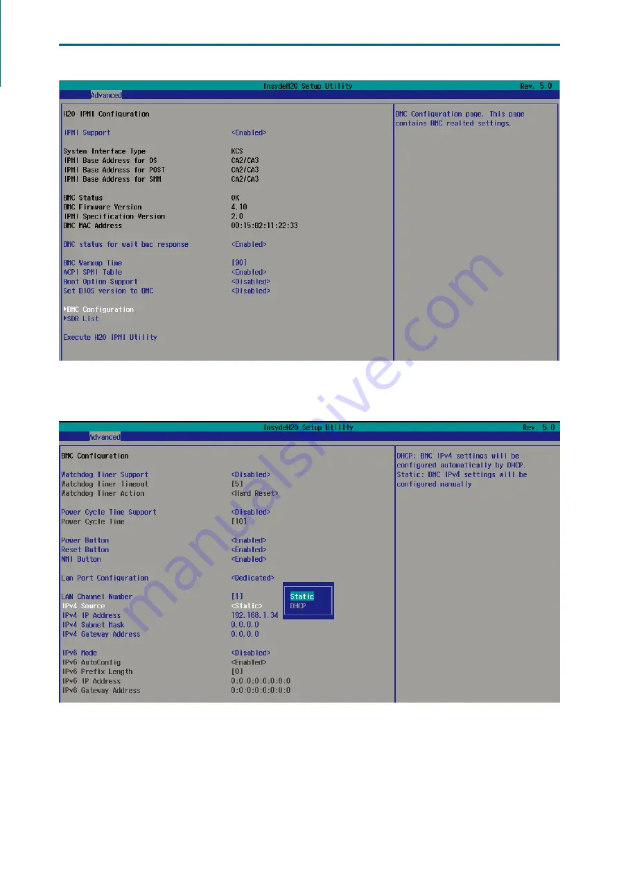
Page 71: ...lugging the Ethernet LAN cable into the BMC LAN port There are two methods to setup BMC IP 5 1 Method 1 Use the BIOS Setup 1 BIOS SETUP Advanced H2O IPMI configuration BMC Configuration IPv4 source St...
Page 72: ...63 SB403 VG User Manual Chapter 5 BMC Configuration Settings...
Page 73: ...64 Chapter 5 BMC Configuration Settings SB403 VG User Manual 2 Input the IP address Set static IP 3 Input the subnet mask address...
Page 74: ...ual Chapter 5 BMC Configuration Settings 5 2 Method 2 Use a Dos Tool Syscheck 1 Type in sc lanset 2 Modify the IP setting NOTE Type 1 for selecting static IP mode or Type 2 for selecting DHCP mode 3 I...
Page 75: ...anual 4 Input the submask address The IP address below is an example using a default IP setting Users are allowed to change the IP address for realistic use 5 Finish the BMC IP configuration NOTE Type...
Page 76: ...dress is configurable 1 Open the browser and type in the default BMC IP address 192 168 22 22 2 Use the default user name and password for first time login to BMC WEB GUI Field Default UserName admin...
Page 77: ...68 Chapter 5 BMC Configuration Settings SB403 VG User Manual 3 Dashboard 4 Sensor Readings 5 Settings Refer to AIC BMC User Guide for more information on AIC BMC...
Page 78: ...al Chapter 5 BMC Configuration Settings Mouse Mode setting For Windows OS environment set mode to absolute For Linux OS environment set mode to relative For SLES 11 OS environment set mode to other mo...
Page 79: ...70 Chapter 5 BMC Configuration Settings SB403 VG User Manual Environmental setting...
Page 80: ...d to unplug AC power cord to reset BMC for the updated new fuction to work properly 1 Boot to the DOS MS DOS or Free DOS is workable 2 Enter BMC firmware directory XXXXXZYY XXXXX project name YY firmw...
Page 81: ...aicipc com tw North California United States Address 48531 Warm Springs Boulvard Suite 404 Fremont CA 94539 United States Tel 1 510 573 6730 Fax 1 510 573 6729 Sales Email sales aicipc com Support Em...