AIC HA202-PH User Manual Download Page 33

25

Chapter 2 Hardware Setup

HA202-PH User's Manual

2�9 Removing and Installing the Battery

2.9.1 Removing the battery

Step 1

 Remove screws x 4 on the bracket kit containing the battery.

Step 2

 Remove the braket kit.

Step 3

 Remove the battery from the bracket kit.

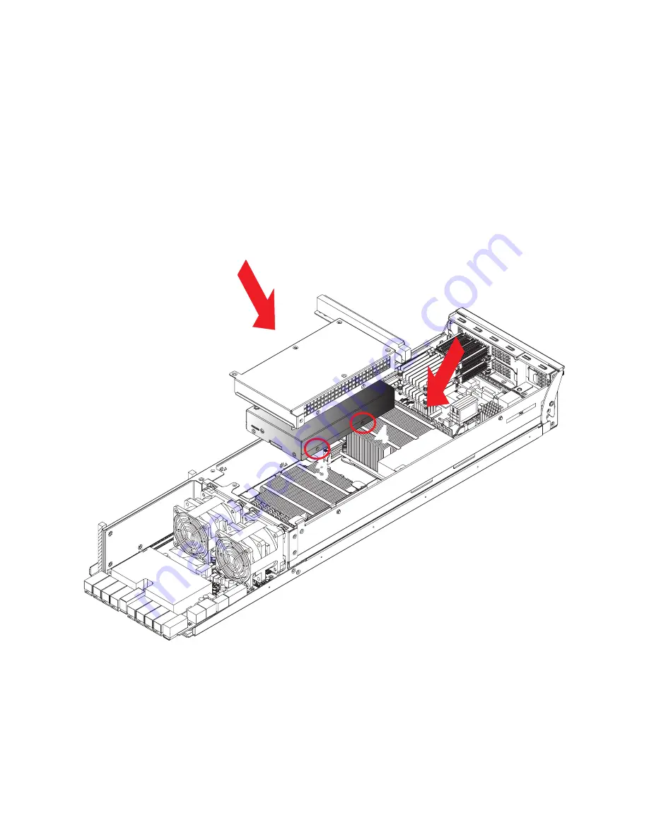
2.9.2 Installing the battery

Step 1

 Place the battery into the bracket kit and attach it to the enclosures

Step 2

 Secure the screws x 4.

1

2

3

4

3

4

Summary of Contents for HA202-PH

Page 1: ...HA202 PH Storage Server Barebone User s Manual UM_HA202 PH_v3_052518...

Page 2: ...Removing and Installing the Fan Module 20 2 6 Removing and Installing the Power Supply Unit Module 22 2 7 Removing and Installing the HDD Backplane Module 23 2 8 Removing and Installing the Solid Sta...

Page 3: ...9 5 2 Method 2 Use a Dos Tool Syscheck 52 5 3 Connect to BMC 54 5 4 Updating BMC Firmware 58 Chapter 6 Hardware Specification 59 6 1 Backplane 59 6 2 Bridge Board 61 6 3 Daughter Board 64 6 4 Interpos...

Page 4: ...Copyright 2017 AIC Inc All Rights Reserved This document contains proprietary information about AIC products and is not to be disclosed or used except in accordance with applicable agreements...

Page 5: ...eption It is essential that only the supplied power cord be used 2 Use only shielded cables to connect I O devices to this equipment 3 You are cautioned that changes or modifications not expressly app...

Page 6: ...unit chassis for a few seconds This will help to discharge any static electricity on your body Place this equipment on a stable surface when install A drop or fall could cause injury Please keep this...

Page 7: ...exposed to moisture 4 The equipment does not work well or will not work according to its user manual 5 The equipment has been dropped and or damaged 6 The equipment has obvious signs of breakage 7 Pl...

Page 8: ...ion Settings This chapter introduces the key features of BIOS including the descriptions and option keys for diverse functions These details provide users to maintain and configure input output device...

Page 9: ...he carton are damaged If any damage is found do not remove the components contact the dealer where the subsystem was purchased for further instructions Before continuing first unpack the subsystem and...

Page 10: ...3 0 2 x16 FHHL Riser Card included per node PSG RC HA2U 24 101 2 PCIe x16 Expander Board per node 1 x 24 port 48 lanes PCI Express NVMe expander board System BIOS BIOS Type FLASH Interface BIOS Featur...

Page 11: ...the noteworthy features of the barebone HA202 PH provides immedi ate and efficient management with Onboard Baseboard Management Controller and greater I O extension Featuring IPMI 2 0 and Aspeed AST2...

Page 12: ...02 PH User s Manual Chapter 1 Product Features Front Panel 24 x 2 5 hot swap drive bays Rear Panel AC 1200W 1 1 redundant high efficiency power supply 80 2 x PCIe 3 0 slots per node 2 x 10 GbE SFP per...

Page 13: ...02 PH User s Manual Chapter 1 Product Features Major Components External 2 5 hot swap PCIe SSD x 24 2 x 60 x 56mm fan modules AIC Server Board Phoenix AC 1200W 1 1 redundant high efficiency power supp...

Page 14: ...th screw 1 and loosen it by giving it two rotations and stop see letter A Step 2 Proceed to screw 2 and loosen it by giving it two rotations and stop see letter B Similarly loosen screws 3 and 4 Repea...

Page 15: ...sor by doing the following 1 Touch the metal chassis before touching the processor or server board Keep part of your body in contact with the metal chassis to dissipate the static charge while handlin...

Page 16: ...te see letter A Step 2 While holding down the lever handle with your other hand lift open the Load Plate see letter B B REMOVE RE M O V E L G A 2 0 1 1 3 S U P P L I E R I D E N T I F I C A T I O N H...

Page 17: ...processor see letter C Carefully place Do NOT drop the CPU into the socket CAUTION The pins inside the CPU socket are extremely sensitive Other than the CPU no object should make contact with the pin...

Page 18: ...n on the locking lever on the CLOSE 1st side see letter A Slide the tip of the lever under the notch in the load plate see letter B Make sure the load plate tab engages under the socket lever when ful...

Page 19: ...llips screwdriver start with screw 1 and engage screw threads by giving it two rotations and stop see letter C Do not fully tighten Step 2 Proceed to screw 2 and engage screw threads by giving it two...

Page 20: ...4 Removing the Processor NOTE Remove the processor by carefully lifting it out of the socket taking care NOT to drop the processor and not touching any pins inside the socket Install the socket cover...

Page 21: ...y position heatsink over the CPU0 and CPU1 and secure the screws Caution Possible thermal damage Avoid moving the heatsink after it has contacted the top of the CPU Too much movement could disturb the...

Page 22: ...4 1333 1600 1866 2133 Registered ECC SDRAM RDIMM Load Reduced DIMM LRDIMM JDIMMB1 SYS PG LED JUSB_INT JPWR2 JDIMMG0 JPWR1 J3 J2 JDIMMG0 JDIMMG1 JDIMMG1 JDIMMH0 JDIMMH0 JDIMMH1 JDIMMH1 JDIMMA0 JDIMMA0...

Page 23: ...DIMM Numbers DIMM ARRANGMENT 2 DIMMs CPU1 CPU0 JDIMM_G0 JDIMM_A0 JDIMMF1 JDIMMD1 JDIMMD0 JDIMMF0 JDIMMG0 JDIMMG1 JDIMMH0 JDIMMH1 JDIMMA0 JDIMMA1 JDIMMB0 JDIMMB1 CPU1 CPU0 4 DIMMs CPU1 CPU0 JDIMM_G0 J...

Page 24: ...JDIMM_C0 10 DIMMs JDIMMF0 JDIMMD0 JDIMMC0 JDIMME0 JDIMMG0 JDIMMG1 JDIMMH0 JDIMMH1 JDIMMA0 JDIMMA1 JDIMMB0 JDIMMB1 CPU1 CPU0 CPU1 CPU0 JDIMM_G0 JDIMM_A0 JDIMM_G1 JDIMM_A1 JDIMM_H0 JDIMM_B0 JDIMM_H1 JD...

Page 25: ...Manual 2 2 2 DIMM Installation Procedure Step 1 Unlock a DIMM socket by pressing the retaining clips outward Step 2 Insert module vertically and press down until it snaps into place Note DIMM notch an...

Page 26: ...s Top Cover 2 3 1 Removing the chassis top cover Step 1 Loosen the screws securing the top covers to the chassis Step 2 Push the cover away from the opposite cover Step 3 Lift the cover to remove 2 3...

Page 27: ...d Installing the Hard Disk Drive 2 4 1 Removing the hard disk drive Step 1 Press the release button on the disk drive Step 2 Pull the disk drive out of the enclosure 2 4 2 Installing the hard disk dri...

Page 28: ...n module Pull the fan module upward to remove it from the fan slot NOTE The heat sink s fans should be blowing toward the rear end of the chassis If one of the fans is facing the wrong direction pleas...

Page 29: ...21 Chapter 2 Hardware Setup HA202 PH User s Manual 2 5 2 Installing the fan module Make sure that the 4 rubbers and connectors are inserted firmly into the slot...

Page 30: ...alling the Power Supply Unit Module 2 6 1 Removing the power supply unit module Step 1 Push the latch and hold the tray handle Step 2 Pull the handle to remove the module out of the enclosure 2 6 2 In...

Page 31: ...Module 2 7 1 Removing the HDD backplane module Step 1 Detach the cables HDDs from the backplane Step 2 Remove the screws x 6 on the module Step 3 Pull the module out of the enclosure 2 7 2 Installing...

Page 32: ...Removing the solid state drive Step 1 Remove the screws x 4 on the bracket kit containing the SSD Step 2 Remove the bracket kit Step 3 Remove the SSD from the bracket kit 2 8 1 Installing the solid st...

Page 33: ...g the battery Step 1 Remove screws x 4 on the bracket kit containing the battery Step 2 Remove the braket kit Step 3 Remove the battery from the bracket kit 2 9 2 Installing the battery Step 1 Place t...

Page 34: ...nual 2 10 Tool less Blade Slide Installation Step 1 Separate the tool less slide rail Pull the inner rail out of the outer rail until it is fully extended Press the locking tab down to release the inn...

Page 35: ...l Step 2 Place the inner rail firmly against the side of the chassis Make sure that the hooks are straight and aligned with the holes in the inner rail Step 3 Slide the inner rail forward until it cli...

Page 36: ...Chapter 2 Hardware Setup 28 HA202 PH User s Manual Step 4 Press the locking tab and push the middle rail back into the outer rail...

Page 37: ...29 Chapter 2 Hardware Setup HA202 PH User s Manual Step 5 Hang the rail hooks on the rack holes and if necessary secure with screws 1 2 Optional Screws...

Page 38: ...Chapter 2 Hardware Setup 30 HA202 PH User s Manual Step 6 Repeat step step 5 to mount the four ends extending the rails as necessary...

Page 39: ...the front of the outer rail and make sure that the ball bearing shuttle is locked at the front of the middle rail Step 8 Align the inner rails with the middle rails and then push evenly on both sides...

Page 40: ...s the locking tabs on both sides of the chassis simultaneously and push the chassis all the way into the rear of the rack Step 10 optional If additional security is required secure the chassis handles...

Page 41: ...ECC DDR 4 1333 1600 2133 2400 TDP 6 1W Wellsburg PCH Port1 IOU2 PCI E Gen3 8GT s X8 SFP x2 XL710 82599 SATAPort 0 5 SATA 0 SATA 1 SATA 2 SATA 3 Port 3a x8 support NTB Golden Finger X16 Golden Finger...

Page 42: ...LCM RJ45 RJ45 VGA COM USB 3 0 USB 3 0 JUSB_INT JVGA_INT RSMRST LED RSMRST LED RSMRST LED JPCH_GPIO JPMBUS JPMBUS JDOM_PWR JSPKR JBUZZER JCPU_XDP JBMC_I2C10 JBMC_I2C10 JBAT JBAT JPWR2 JPWR1 SYS PG LED...

Page 43: ...35 Chapter 3 Motherboard Settings HA202 PH User s Manual 3 3 Motherboard Content List...

Page 44: ...T JUSB_INT JBMC_DP JCOM4 JBMC_GPIO JLCM RJ45 RJ45 VGA COM USB 3 0 USB 3 0 JUSB_INT JVGA_INT RSMRST LED RSMRST LED RSMRST LED JPCH_GPIO JPMBUS JPMBUS JDOM_PWR JSPKR JBUZZER JCPU_XDP JBMC_I2C10 JBMC_I2C...

Page 45: ...CH FAN6_TACH FAN5_TACH FAN4_TACH FAN3_TACH FAN2_TACH FAN1_TACH PWM4 PWM3 PWM2 PWM1 3 3V_DUAL 3 3V_DUAL 3 3V 3 3V GND SYS_HEALTH HD_LED 3 3V_DUAL UID_SW_IN_N FP_NMI_BTN SW_RST_BTN SW_PWR_BTN JFRNT JFRN...

Page 46: ...s Jumpers SCOM2_T3OUT SCOM2_R4IN GND E JBMC_DP GND I2C9SDA I2C9SCL EXTRST BMC_GPY1 BMC_GPY0 F JBMC_GPIO G JBMC_I2C1 I2C1SDA GND I2C1SCL NC CLK_33M_DP80 PCH_LFRAME_N RST_PLTRST_N PCH_LPC_LAD3 3 3V PCH_...

Page 47: ...s Jumpers Heart Bit LED UID LED JPCH_GPIO JINTRUDER RSMRST LED RSMRST LED RSMRST LED JPCH_GPIO JPMBUS JPMBUS JSGPIO JSGPIO JDOM_PWR JSPKR JBUZZER JBMC_I2C10 JBMC_I2C10 J3 J2 J2 J3 JCMOS JBMC_RST J4 JB...

Page 48: ...CH_FP_USB3_RX_P2 GND PCH_FP_USB3_TX_N2 PCH_FP_USB3_TX_P2 GND PCH_FP_USB2_N2 PCH_FP_USB2_P2 PCH_USB_OC 23 Internal Connectors Jumpers B JPCH_GPIO PCH_GPIO8 PCH_GPIO21 GND C JPMBUS SMB_PMBUS_CLK SMB_PMB...

Page 49: ...HA202 PH User s Manual SYS PG LED JCPU_XDP JPWR2 JPWR1 SYS PG LED JPG_LOCK JPG_LOCK A B Internal Connectors Jumpers A JPWR2 8 12V 12V 12V 12V GND GND GND GND B JPWR1 GND GND GND GND GND GND PS_ON 12V...

Page 50: ...ight Upward Triangle Yellow Blinking 1G link detected activity detected 82599 Activity detected XL710 NIC 1 Left Upward Triangle Green Blinking 10G link detected activity detected 82599 1 10G link det...

Page 51: ...t active SYS PG LED ON System power good ready OFF System power good is not ready RSMRST PG LED ON Resume Well Reset ready OFF Resume Well Reset is not ready UID LED ON UID activity detected OFF UID n...

Page 52: ...TB Setting Short Downstream port Open Upstream port Default Default C JBMC_DIS JBMC_DIS Setting Short Disable Open Normal Default D J3 J3 Setting Short BIOS Recovery Mode Open Normal Default E J2 J2 S...

Page 53: ...guration Settings Step 1 Press ESC to run the setup procedure Caution When Quiet Boot IS enabled OEM LOGO WILL BE displayed INSTEAD OF POST MESSAGES Step 2 Click SCU to enter the Setup menu Caution Fo...

Page 54: ...46 Chapter 4 BIOS Configuration Settings HA202 PH User s Manual Step 3 Identify the BIOS Version Step 4 Load Optimal Default setting Step 5 Save the setting and exit the BIOS setup utility...

Page 55: ...SB mass storage device Step 2 Put the BIOS bin file and mflash cfg in Root directory Step 3 Plug the USB mass storage device into a USB port of the target computer Step 4 Turn on the system Step 5 Boo...

Page 56: ...ment If you need to update Flash in the DOS environment please use H2offt d utility To use this utility you must include the flash bat H2offt d exe and bin file in the same folder Please follow the in...

Page 57: ...ter 5 BMC Configuration Settings Insert Ethernet LAN cable into the BMC LAN port There are two methods to setup the BMC IP 5 1 Method 1 Use the BIOS Setup Step 1 Click BIOS Setup Advanced H2O IPMI con...

Page 58: ...Chapter 5 BMC Configuration Settings HA202 PH User s Manual 50 Step 2 Type in the IP address Configure the static IP...

Page 59: ...Chapter 5 BMC Configuration Settings HA202 PH User s Manual 51 Step 3 Type in the subnet mask address...

Page 60: ...ettings HA202 PH User s Manual 52 5 2 Method 2 Use a Dos Tool Syscheck Step 1 Type in sc lanset Step 2 Modify the IP setting Step 3 Type in the IP address Note type 1 for selecting static IP mode or t...

Page 61: ...53 Step 4 Type in the submask address Below IP address is an example using a default IP setting User is allowed to change the IP address for realistic use Step 5 Complete the BMC IP configuration Note...

Page 62: ...address is configurable Step 1 Open the browser then type default BMC IP address 192 168 22 22 Step 2 Use the default user name and password for first time BMC WEB GUI login Field Default UserName adm...

Page 63: ...on Settings HA202 PH User s Manual 55 Dashboard The Dashboard page gives the overall information about the status of a device Server Health Sensor Readings The Sensor Readings page displays all the se...

Page 64: ...s group of pages allows you to access various configuration settings Mouse Mode Settings The KVM Mouse Setting page allows you to configure the mouse mode to relative absolute and other For Windows OS...

Page 65: ...on Settings HA202 PH User s Manual 57 Remote Control The Remote Control page allow you to access any of the managed devices within your system Environmental Setting Press ALT C for local and remote OS...

Page 66: ...is is just an example The latest BMC firmware version is available from the FAE or AIC website Step 4 After update BMC firmware please power off and then power on the system Please refer to Aspeed AST...

Page 67: ...ter 6 Hardware Specification HA202 PH User s Manual 59 Chapter 6 Hardware Specification This chapter provides detailed instruction guide on hardware instruction 6 1 Backplane 6 1 1 Backplane Layout J1...

Page 68: ...5V GND GND GND 3 3V 5V_AUX PS_ON POWER OK POWER_FAULT_N1 POWER_FAULT_N2 GND GND GND GND GND GND GND GND GND GND GND GND 12V 12V 12V 12V 12V 12V 12V 12V POWER_SW CANISTER_P_PON CANISTER_S_PON 3VSTBY 3V...

Page 69: ...Chapter 6 Hardware Specification HA202 PH User s Manual 61 JVBATT1 JVBATT_I2C1 JIPMI_LOC1 JPWR2 JPWR1 J13 J14 J15 6 2 Bridge Board 6 2 1 Bridge Board layout...

Page 70: ...pers 12V input from Battery JVBATT1 12V 5VSB 6A per pin output JPWR1 IPMI JIPMI_LOC1 Battery PMBUS JVBATT_I2C1 12V 12V 12V 12V GND GND GND GND 12V 12V 12V 12V 12V 5VSB PSOK PSON GND GND GND GND GND GN...

Page 71: ...s Manual 63 JPWR_SW1 FAN J11 FAN J12 12V output JPWR2 HDD PWR JHDDPWR1 SW_PWR_BTN MB_SW2 HW1_TACH_FAN1 12V_FAN PWM1_R HW1_TACH_FAN2 12V_FAN GND HW2_TACH_FAN1 12V_FAN PWM2_R HW2_TACH_FAN2 12V_FAN GND...

Page 72: ...Manual 64 6 3 Daughter Board 6 3 1 Daughter Board layout 6 3 2 Internal Connectors Jumpers POGO Pin J1 SW_BUTTON SW1 SW_BUTTON SW2 SW_BUTTON SW3 SW_BUTTON SW4 J1 SW4 SW3 SW2 SW1 SW1_P_R SW2_P_R SW3_P_...

Page 73: ...r 6 Hardware Specification HA202 PH User s Manual 65 6 4 Interposer Board 6 4 1 Interposer Board layout 6 4 2 Internal Connectors Jumpers J201 GPIO_C VS0_RST VS1_RST GND GPIO_A GPIO_B PEX_SCL0_R PEX_S...

Page 74: ...Chapter 6 Hardware Specification HA202 PH User s Manual 66 J1 CN2 CN1 JHDD_PWR JUSB1 J2 6 5 Riser Card 6 5 1 Riser Card layout...

Page 75: ...Chapter 6 Hardware Specification HA202 PH User s Manual 67 6 5 2 Internal Connectors Jumpers PCIe slim x8 slot CN2 1...

Page 76: ...Chapter 6 Hardware Specification HA202 PH User s Manual 68 PCIe slim x8 slot CN2 2...

Page 77: ...Chapter 6 Hardware Specification HA202 PH User s Manual 69 100 x 2 Pin Sametc HSEC8 200p slot CN1 1...

Page 78: ...Chapter 6 Hardware Specification HA202 PH User s Manual 70 100 x 2 Pin Sametc HSEC8 200p slot CN1 2...

Page 79: ...HDD_PWR USB 2 0 JUSB1 External thermal sensor J2 GND 12V 12V GND GND 5V 5V_USB USB1_D USB1_D GND GND 5V_USB USB0_D USB0_D GND NC BMC_EXTRST GND BMC_GPY0 BMC_GPY1 GPIOA4_SCL9 GPIOA5_SDA9 GPIOC0_SCL10 G...

Page 80: ...Chapter 6 Hardware Specification HA202 PH User s Manual 72 6 6 Drive Slot Map HBA CARD MegaRaid CARD...

Page 81: ...tw CHINA Tel 86 21 54961421 86 21 54961422 Fax Extension 608 Email Technical Support support aicipc com AMERICA West coast Tel 1 909 895 8989 Fax 1 909 895 8999 Email sales aicipc com AMERICA East coa...

Reviews: