AI-Tek Instruments TACHTROL 3 Instruction Manual Download Page 16

The shaft driving the incoming roller is turning at 1000 rpm, and the shaft driving the outgoing roller
is turning at 1250 rpm. 

You want the tachometer to:

1. Compute Speed A (Incoming roller) and Speed B (out-going roller) in FPM.

SF fpm = 60 x 

π

 x D’ = 60 x 3.1416 x 3’ = 565.4880

PPR                 48                  48

C

1

= 565.5

C

2

= 48.00

C

3

= 565.5

C

4

= 48.00

2. Send the percentage of elongation to Display, ratio to Setpoints I and 2, and Speed B only to

Analog Output.

C

11

=   x  5  5  2  9

3. Have Display show FPM with autoranging fixed to one decimal place.

C

5

=1000

C

12

=                 1

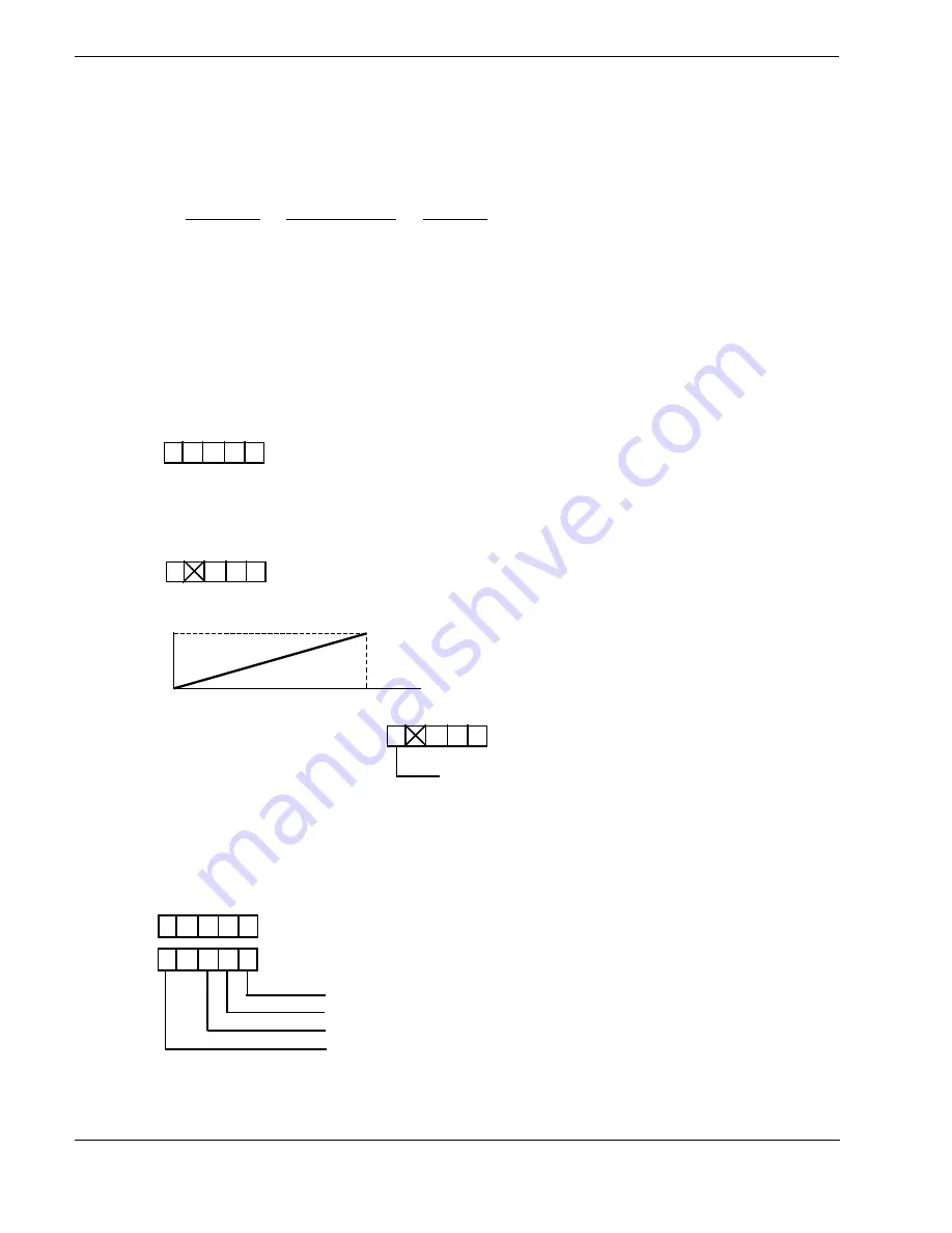
4. Have the Analog Output drive an auxiliary 4 - 20mA recorded which has a range of 0 to 5000fpm.

20mA

4mA

0             fpm              5000

C

6

= 0000

C

12

=                 1

C

7

= 5000

blank

5. Use the setpoints for web break detection, with Setpoint 1 going to alarm if the ratio is less than

0.5, and Setpoint 2 going to alarm if the ratio is less than 1.0. Relays are latching.

C

8

= 0.500

C

9

= 1.000

C

10

=  x  0  0  0  0  (no hysteresis)

C

12

=      x  5  5  1

autoranging fixed to one decimal place
latching relay
latching relay
analog output is 4 - 20mA

12

Summary of Contents for TACHTROL 3

Page 1: ...TACHTROL 3 ...

Page 2: ...152 Knotter Drive P O Box 748 Cheshire CT USA 06410 0748 www aitekinstruments com Phone 1 800 643 0643 7 04 Printed in U S A AI TEK INSTRUMENTS LLC 13010 D 7 04 Printed in U S A ...

Page 3: ...LECTING THE MATHEMATICAL FUNCTIONS 6 4 3 DEFINING THE BEHAVIOR OF THE OUTPUTS 7 4 3 1 Display 7 Autoranglng 7 4 3 2 Analog Output 7 Zero Scale 7 FullScole 8 4 3 3 Setpolnts 8 Setpoint Types 8 Setpoint Behavior 8 Latchlng Auto Reset 9 4 3 4 Sample Set Ups 10 Single Channel Operations 10 Dual Channel Operation 11 4 4 ENTERING THE CONSTANTS 13 4 4 1 Control Features 13 4 4 2 Turning On The Power 14 4...

Page 4: ...OR S 20 6 1 MOUNTING THE SPEED SENSOR S 20 6 2 SETTING THE CLEARANCE 20 6 3 TYPICAL WIRING CONNECTIONS FOR AI TEK SENSORS 20 6 3 1 Passive Sensors 21 6 3 2 Active Sensors 22 6 3 3 BI Directlonal Sensors 22 7 0 APPENDIX TIME MODE OPERATION 23 SPECIFICATIONS 23 INSTALLATION AND WIRING PRACTICES FOR ELECTRONIC INSTRUMENTATION CONTROL 25 WARRANTY 27 ...

Page 5: ...ter may be used as a bi directional tachometer to measure speed with direction indication from an AI Tek bi directional sensor 2 1 MATHEMATICAL FUNCTIONS 2 1 1 Single Channel Operation Used as a single channel instrument the TACHTROL 3 tachometer can compute Speed A or Speed B 2 1 2 Dual Channel Operation Used as a dual channel instrument the TACHTROL 3 tachometer can compute unrelated Speed A and...

Page 6: ...he mathematical functions to the outputs and define the behavior of each output Figure 1 illustrates the flow of data in the TACHTROL 3 tachometer Figure 1 Data Flow Diagram 2 C5 ADDITIONAL SCALING FACTOR C12 DIGIT 1 DECIMAL LOCATION C6 ZERO SCALE C7 FULL SCALE C12 DIGIT 5 0 20 4 20 mA C8 SETPOINT C10 DIGITS 1 2 HYSTERESIS C12 DIGIT 2 RELAY LOGIC C9 SETPOINT C10 DIGITS 3 4 HYSTERESIS C12 DIGIT 3 R...

Page 7: ...constant Display shows the computed function of channel A or channel B However C5 can be altered to convert one engineering unit to another for Display purposes only For example C5 can be used to configure the instrument so that RPM is being com puted and FPS Is being displayed This Is Illustrated by the following equation Arpm x C5 Dfpm where A scaled Input signal frequency D display value C6 set...

Page 8: ...cal Functions 3 Defining the Behavior of the Outputs 4 Entering the Constants 5 Storing the Constants 6 Selecting the Input Options 4 1 FINDING THE SCALING FACTORS C1 THRU C4 If you are using the TACHTROL 3 tachometer as a single channel Instrument to measure RPM and are using a 60 tooth gear skip this section and proceed to section 4 2 Selecting The Mathematical Functions 4 1 1 Finding the Scalin...

Page 9: ... 48 1 π always 3 1416 You can improve the accuracy of the scaling factor by manipulating the fraction in a way that uses the full 4 1 2 digits that can be entered on the Display In this example the two 4 1 2 digit scaling factors are used to scale the channel with 5 digits of accuracy 7 8512 7 8512 x 10000 78512 4 19628 1 1 10000 10000 4 2500 For IPM YPM IPS and FPS the formulas for finding the sc...

Page 10: ...nits The general formula is DISPLAY VALUE SCALING FACTOR INPUT SIGNAL FREQUENCY To solve this problem 1 Pick a display value within the range of your operation 2 Calculate the Input signal frequency produced by the speed sensor at the display value you ve picked Frequency is simply the number of electrical pulses produced by the sensor in one second All AI Tek sensors produce 1 pulse each time a g...

Page 11: ... any type of limit switches when using Function 4 A Note With dual channel operation when ratio and elongation functions are selected Functions 5 6 and 9 the ratio of zero over zero by definition is unity 1 4 3 DEFINING THE BEHAVIOR OF THE OUTPUTS 4 3 1 Display You can program the Display to show the computed function of channel A and or channel B and you can configure the instrument to compute in...

Page 12: ...l focus on the latter type of application Setpoint Types There are two types of setpoints underspeed and overspeed Underspeed relays trigger events when frequency drops below the setpolnt FIGURE 2 UNDERSPEED SETPOINT Overspeed relays trigger events when the frequency rises above the setpolnt FIGURE 3 OVERSPEED SETPOINT Setpoint Behavior Relay setpoints may be configured to either energize or de en...

Page 13: ...esis prevents chatter the clicking on and off of the relay as frequency hovers around the setpoint value Hysteresis is specified as a percentage of the setpoint value The position of hysteresis above or below the setpoint is determined by the relay type Overspeed relays have hysteresis below the setpoint Underspeed relays have hysteresis above the setpoint Figure 4 shows an overspeed relay with hy...

Page 14: ... to 1 Compute Speed A in RPM SF C1 60 60 10 C2 PPR 24 4 C1 10 000 C3 and C4 are not adjusted C2 4 000 C3 and C4 are not adjusted 2 Send Computed Function Speed A to All Outputs Speed A 1 on Function Chart C11 X 1 1 1 1 x denotes unused digit 3 Have Display Show FPM with Autoranging to Two Decimals right only A x C5 Display value RPM x FPR FPM 10 Overspeed hysteresis below setpoint de energize abov...

Page 15: ... an Alarm condition when the speed rises above lOOOrpm and automatically come out of Alarm when it returns to 950rpm Overspeed Failsafe C8 600 C9 1000 C10 X 0 5 1 0 C12 1 X 0 1 6 autoranging to two decimals right only underspeed failsafe overspeed failsafe analog output is 0 20 mA Dual Channel Operation Suppose you are using the tachometer as an elongation monitor in a paper mill Elongation is the...

Page 16: ... only to Analog Output C11 x 5 5 2 9 3 Have Display show FPM with autoranging fixed to one decimal place C5 1000 C12 1 4 Have the Analog Output drive an auxiliary 4 20mA recorded which has a range of 0 to 5000fpm 20mA 4mA 0 fpm 5000 C6 0000 C12 1 C7 5000 blank 5 Use the setpoints for web break detection with Setpoint 1 going to alarm if the ratio is less than 0 5 and Setpoint 2 going to alarm if t...

Page 17: ...ant being displayed can be altered by using the DTW and the Pb When the DTW is set to O pushing and holding the Pb locates the decimal When the DTW is set to a Display digit pushing and holding the Pb changes the number in the digit Push Button Pb TTL MAG Dipswitches Four possible settings program the instrument for the type of sensor being used A O Full Scale R31 is factory set and normally will ...

Page 18: ...ave a 60 tooth gear then frequency is equal to RPM and the constants are equal to 1 the standard constant 1 Use two 4 1 2 digit numbers in the form of a fraction to enter each of the scaling factors 2 For Frequency A enter the numerator in C1 and the denominator in C2 For Frequency B enter the numerator in C3 and the denominator in C4 If you are using the TACHTROL 3 tachometer as a single channel ...

Page 19: ...y digit 4 Turn DTW to 3 enter the number of the function you have selected to send to setpoint 1 by pushing and holding the Pb until the number appears in the third Display digit 5 Turn DTW to 4 enter the number of the function you have selected to send to setpoint 2 by pushing and holding the Pb until the number appears in the fourth Display digit Select the number of the function from the table ...

Page 20: ... 7 B Enter constant by using the DTW and Pb in the same manner as you did for C1 thru C6 3 Zero Scale Current A Turn CTW to 12 B Turn DTW to 5 C Select the zero scale current from chart 0 or 4ma D Push and hold Pb until the number representing the zero you ve selected appears in the fifth Display digit ANALOG OUTPUT IS 4 20ma blank C12 OR 0 20ma 1 Setpoint 1 Output 1 Setpoint Constant A Turn CTW t...

Page 21: ...presenting the logic you ve selected appears in the second Display digit Setpoint 2 Output 1 Setpoint Constant A Turn CTW to 9 B enter the constant using the DTW and Pb in the same manner as you did for C1 thru C8 2 Hysteresis for Setpoint 2 A Turn CTW to 10 B Enter the value of the hysteresis given in percent as a two digit number C Turn DTW to 3 Push and hold Pb until the value of the first digi...

Page 22: ... inputs it is also necessary to connect the negative input on the terminal block to the common terminal with a wire number as shown In the wiring diagram Note A passive sensor may be used with one channel and an active sensor with the other Note Both active and passive inputs present a 2000 ohm load to the sensors Now that you have finished entering the constants and input options the instrument i...

Page 23: ...2 NEMA 4X 3 X STYLE 4 LESS ENCLOSURE STYLE 19 ...

Page 24: ...use Active Sensors to cease operation CAUTION AT NO TIME IN ITS REVOLUTION SHOULD THE GEAR TOUCH THE SENSOR OR DAMAGE MAY OCCUR When you have set the clearance check the setting to see that a complete revolution of the gear does not in any way contact the sensor Proper orientation of Active Sensors is also required Flats on the housing must be in the same plane as the gear See diagram below If you...

Page 25: ... AI Tek Industrial Products Catalog The pulse signal for channel A enters the instrument through terminals 1 freq and 2 freq The pulse signal for channel B enters the instrument through terminals 4 freq and 5 freq 6 3 1 Passive Sensors The figure below illustrates the use of a Passive Sensor connected to channel B producing an AC signal Refer to the AI Tek Instruments Products Catalog for informat...

Page 26: ... the same way Note connect 2 and 7 with jumper 6 3 3 Bi Directional Sensors These sensors have basically the same wiring as Active Sensors When set up for bi directional operation The TACHTROL 3 tachometer reads the B input to determine direction You can choose which direction is considered minus direction by orienting the sensor Rotate the sensor through 180 to reverse the operation of the minus ...

Page 27: ...asured at I KHz Active Pickup TTL duty cycle 20 to 80 DC pickup power 12 VDC 100 mA will power two 2 zero velocity pickups or one 1 bi directional pickup Bi Directlonal Pickup One 1 frequency input TTL input A and the direction input TTL input B from a Bi Directional pickup High 5v indicates positive direction and only single speed functions Speed A are useful when connected in this operation mode...

Page 28: ...t digit Analog 3 of range Response Times Display updated approx every 1 2 sec based on latest available input measurement s Analog Relay Outputs updated at a variable rate depending on the frequency The typical maximum response times are Above 100 Hz 100 milliseconds typical 200 milliseconds maximum 2 Hz to100 Hz 2 cycles 30 milliseconds typical 6 cycles 30 milliseconds maximum Below 2 Hz Measurem...

Page 29: ... balanced inputs such as magnetic pickup inputs should be accomplished by switching both inputs The switching of just one input creates an unbalanced line and introduces additional electrical noise to low level signals 7 The use of commutators or slip rings in transmitting low level signals is not recommended Should this practice be absolutely necessary care must be exercised that the point of con...

Page 30: ...T BREACH OF WARRANTY TORT OR OTHERWISE BE LIABLE FOR CONSEQUENTIAL INCIDENTAL SPECIAL OR EXEMPLARY DAMAGES including but not limited to loss of profits or rev enues loss of use of or damage to any associated equipment cost of capital cost of substitute products facilities or services downtime costs or claims of Buyer s customers b SELLER S LIABILITY ON ANY CLAIM OF ANY KIND FOR ANY LOSS OR DAMAGE ...

Reviews: