

This display is designed for indoor use in a landscape orientation, and to be mounted with a bracket meeting
VESA specifications. Brackets capable of supporting at least 100 kg must be used. Mounting the monitor
requires the work of a trained AV professional and AHA cannot be held accountable for accidents or injuries
due to improper mounting.
For Child Safety
- If mounting the display using the provided support feet, insure that they are bolted to the
surface holding the display and that the furniture is properly secured
- Only use furniture that can support the weight of the display
- Do not allow the monitor or feet to hang over the edge of the supporting furniture.
- Do not place the monitor on furniture that could be utilized as steps, such as a cabinet
or chest of drawers.
- Route and secure cables so that they are not accessible by children.
Mount your display as described, yet be sure to follow the Safety Precautions as mentioned on page 2 and 3.
If you have been provided with a pen tray, follow the instructions below to mount it to the display. Remember
this add-on is designed to hold small writing tools and accessories used when operating the display. The pen
tray should never be used to store heavy objects, as a step, or as a ledge to hang materials from.
Find a suitable, a ventilated location to mount the display. Ensure that any cabinets or structures
surrounding the display meet the provided dimensions to allow for proper ventilation and operating
temperature.
1.
Ensure that the wall, stand, mount, or other support is capable of supporting the 100 kg display. The
mount must be flat so that the display will operate perpendicularly to the floor. This display should never
be mounted and operated on its back.
The acceptable storage temperature range is -20℃~60℃. The acceptable operating temperature
range is 0℃~35℃. Ensure the mounting location does not exceed these ratings.
Ensure the location where the display will be mounted is out of direct sunlight.
In order to prevent malfunctions(touch sensor), we strongly recommed that do not place the halogen
Lamp in of interactive display.
If the display came with support feet attached, remove them by unscrewing their 4 bolts on the rear of
the display. Lift the display by its handles to remove the support feet from the bottom.
Attach your VESA compatible bracket to the rear of the display using the mounting holes shown in the
picture below.
2.
3.
4.
5.
6.
7.
Install the mounting brackets to the rear of the display using the screws provided.
1.
Carefully lift and place the display by its handles into position on the bracket. Ensure that the display is
centered and angled to satisfaction.
Ensure that cables are securely attached and fixed. Make sure they are routed and stored so that they
will not be stepped on.
8.
9.
Connect the LED display’s power cord to the display and the appropriate electrical plug.
Turn the display on by pressing the Power button on the display or remote.
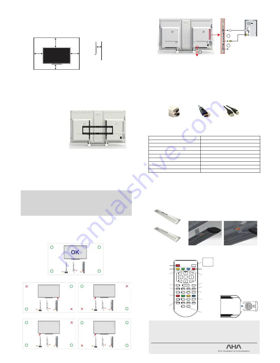
Using an RGB connection to display video from your computer:
- Connect the 15-pin RGB port on the back of your LED Display to the 15 pin RGB port on the
computer. To make this connection you should use an RGB cable with male adapters on both ends.
Using an HDMI connection to display video from your computer:
- Connect the HDMI cable from your computer’s HDMI port to the display’s HDMI port.
To make this connection, you should use an HDMI cable with male adapters on both ends.
Using the USB (TOUCH) connector on the PC USB terminal:
If you want to use your display’s touch sensing capability, you must connect a USB cable from the
display to your computer or device. You must use a USB cable with both A and B type adapters. B type
will attach to the rear of the display, and A type will attach to your computer.
1.
2.
3.
Mounting the Display
Connection
Specification
Mounting the Pen Tray (Option)
5cm
5cm
25cm
10cm
10cm
(VESA Mounting Demension 600x400)
Align the pen tray above the brackets so that its threaded tracks line up
to the brackets’ holes. Ensure that the pen tray is centered with the
display. Install the eight holding screws from underneath the pen tray.
2.
Connecting a Computer
15 Pin RGB connector
HDMI connector
USB (type A/B)
1
2
3
AC IN
RGB
HDMI
USB For Touch
Model
Power Supply Voltage
Power Consumption
Operating Temperature
Touch Detection method
Effective screen size(mm)
Overall dimensions (with stand) mm
Overall dimensions (without stand) mm
Weight
Operating humidity
CSLED-84
AC100 - 240V, 50/60Hz, 4.4/1.9A
150 ~ 430W
0℃ ~ +35℃
Optical image sensor system
1,860.48(W) x 1,046.52(H)
1,974(W) x 1,243(H) x 280(D)
1,974(W) x 1,160(H) x 101(D)
Approx. 95Kg
20% to 80% (no condensation)
Customer support call center : +82 31-997-0909
http://www.ahatouch.com
Headquarter and 1st factory
3011, Hakwoon-Ri Yangchon-meyon, Kimpo-City, Kyounggi-do, 415-843, Korea
2nd factory
#301 Ka-dong Techno-Zone, 2979, Hakwoon-Ri Yangchon-meyon, Kimpo-City, Kyounggi-do, 415-843, Korea
3rd factory
#510-5, Daekok-Dong, Seo-Ku, Incheon City, 404-280 Korea
Pen Tray(AHA-P300)
Pen Tray(AHA-P400)
- 6 -
- 8 -
- 5 -
- 7 -
How to insert the battery
Insert the battery with the polarities
facing as shown. + facing the
bottom of the remote and
–
facing
upwards.
Remote Control
COMPONENT(Option)
AV(Option)
S-VIDEO(Option)
SCART(Option)
PC
HDMI 1
HDMI 2
HDMI 3
DP
HDMI 1
HDMI 2
HDMI 3
DP
Hot Key
Select Input Source
Turns the LCD Display ON and OFF
SLEEP
NUMBER KEY(Not Used)
STEREO
MONO
FREEZE
EXIT
PICTURE MODE
Dynamic
Standard
Mild
Game
User
SOUND MODE
Flat
Music
Movie
Speech
User
ASPECT
16:9
4:3
CURRENT INFORMATION
INPUT
OK
POWER
PC
HDMI
COMP.
AV
VOL+
VOL-
EXIT
FREEZE
MUTE
STEREO
SLEEP
PSM
1
2
3
4
5
6
7
8
9
0
SSM
ASPECT
MENU
INFO
SOURCE
설치환경에 따라 제품의 평탄도가 맞지않으면 터치센서 작동오류가 발생하오니 이때는 동봉된 CD의
Flatness checking.exe 파일을 실행하고 화면의 지시처럼 점멸하는 화살표 방향에 괴임목으로 받쳐줍니다.
<그림과 같이 제품 하단부에 괴임목을 받쳐 넣어 반드시 OK라는 글자가 화면에 표시되도록 조절해야 합니다>
센서가 전부 OK 일때 제품 중앙에 OK 표시.화살표 없음.
센서가 아래 그림일 경우 화면 우측 하단에 화살표
점멸
센서가 아래 그림일 경우 화면 좌측 하단에 화살표
점멸
센서가 아래 그림일 경우 화면 우측 하단에 화살표
점멸
상기 이외의 경우도 같은 방법으로 화살표 표시
센서가 아래 그림일 경우 화면 좌측 하단에 화살표
점멸
제품 설치시 평탄도 조정 방법


