Agri-Fab 45-03261 Owner'S Manual Download Page 13

13

WHEEL GEAR AND PAWL SERVICE

ImPORTANT:


Do not

 remove both wheels at the same 

time to avoid mixing of parts. (The R.H. and L.H. ratchet 
gears are not interchangeable.) 

make notes

 on the position 

of washers and snap rings during disassembly.

1.  Remove 

only one

 wheel from the sweeper.

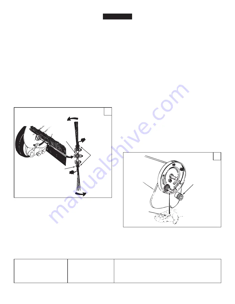
2.  Remove the retaining rings and washers which hold the 

ratchet gear onto the brush shaft.

3. 

(Figure 27)

 Remove the gear by sliding it off the brush 

shaft. (Look for the drive pin, which may fall out of the 
brush shaft when the ratchet gear is removed.)

4.  To  reassemble,  insert  the  drive  pin  through  the  hole 

near the end of the brush shaft. Make sure the pin slides 
back and forth easily in the shaft.

5.  Lightly grease the shaft and fill the ratchet gear with 

grease.  Assemble  the  ratchet  gear  back  onto  the 
shaft.

6.  Lightly grease the axle and the gear teeth on the wheel, 

and then reassemble the wheel.  The brushes should 

rotate 

only

 during forward rotation of the wheel. If the 

brushes are driven (rotated) by both forward and reverse 
rotation of the wheel, the drive pin is jamming in the 
ratchet  gear.  Disassemble  to  clean  and  lubricate  the 
drive pin and the ratchet gear.

7.  Remove the second wheel and repeat the procedure.

BRUSH REPLACEmENT

NOTE:

  Brush replacement should be done one brush at  


a time.

1.  Remove the hopper bag from the sweeper.

2. 

(Figure 26)

 Loosen the hex bolts and lock nuts on two 

single brush retainers which clamp one brush to the 
double brush retainers. 

Do Not


loosen

 or remove the 

bolts  which  fasten  the  double  brush  retainers  to  the 
brush shaft.

3. 

(Figure 26)

 Slide the brush out of the retainers, noting 

on which side of the brush the bristles overlap. 

4. 

(Figure 26)

 Install new brush, making sure the bristles 

overlap on the same side of the brush as before.

1.  Brushes set too low.
2.  Brushes are jammed
3.  Wheels are jammed.

Wheels skid when sweeping.

1.  Adjust height till brushes are 1/2" down into grass.
2.  Stop sweeper. Remove obstruction.
3.  Remove one wheel at a time to check for obstruction or 

damage. Refer to Service and Adjustments section.

SERVICE AND ADJUSTmENTS

TROUBLESHOOTING

26

27

ENGLISH

BRUSH ROTATION

BRUSH ROTATION

OVERLAP
BRISTLES

OVERLAP
BRISTLES

SINGLE
BRUSH
RETAINERS

DOUBLE BRUSH RETAINER

BRUSH
 SHAFT

RATCHET
GEAR

DRIVE
PIN

Summary of Contents for 45-03261

Page 1: ...No 45 03261 ATTENTION Lire et suivre attentivement les instructions et consignes de s curit de cette notice PRECAUCION Lea cuidadosamente los Procedimientos e Instrucciones para la Operaci n Segura de...

Page 2: ...a 2 12 Tubo de la Parte Posterior de la Tolva 2 13 Tubo Lateral de la Parte Inferior de la Tolva 2 14 Varilla Giratoria de la Golsa de la Tolva 15 Barra de Soporte de la Tolva 2 1 B ti de la balayeuse...

Page 3: ...Hex Bolt 5 16 x 1 F 1 Carriage Bolt 5 16 x 1 G 4 Hex Bolt 1 4 x 1 I 4 Nylock Nut 1 4 J 11 Nylock Nut 5 16 K 4 Flat Washer 5 16 L 1 Star Washer M 1 Hair Cotter Pin 1 8 N 6 Hair Cotter Pin 3 32 ref qty...

Page 4: ...icle and sweeper owners manuals and know how to operate your vehicle and sweeper before using this sweeper attachment Always instruct other users before they operate the sweeper 2 Do not permit childr...

Page 5: ...e brush assembliesasshownsothatthebrushretainersmarked with ink are in the middle with the red one on the right and the black one on the left ENGLISH OVERLAP BRISTLES BRUSH RETAINER MARKED BLACK BRUSH...

Page 6: ...ts A and 5 16 nylock nuts J Do not tighten yet 5 5 16 x 3 HEX BOLT A 5 16 NYLOCK NUT J 3 Figure 3 Attach the brush assembly with the black brush retainer to the left end of the brush shaft using two 1...

Page 7: ...he hitch tubes using two 5 16 x 2 1 14 hex bolts B and 5 16 nylock nuts J The bolts should straddle the front hitch tube bolt Do not tighten yet 9 At this time tighten the four bolts fastening the hit...

Page 8: ...ten together using plastic plugs Z 11 12 ENGLISH REAR HOPPER TUBE brace holes on bottom UPPER HOPPER SIDE TUBE PLASTIC PLUG Z 14 Figure 10 Place the star washer L between the height adjustment handle...

Page 9: ...ble the ends of the rear hopper tube onto the ends of the lower hopper side tubes Fasten together using plastic plugs Z 5 Figure 14 Place the assembled lower hopper tubes into the bottom of the hopper...

Page 10: ...ed sleeve at the front of the wind screen 11 Using a hammer assemble each palnut R onto one end of the hopper pivot rod while bracing the other end against a solid object 12 Figure 17 Assemble a vinyl...

Page 11: ...eeper bag is approximately level and 5 to 7 above the ground See figure 22 for tractor hitches that are 10 to 13 above the ground See figure 23 for tractor hitches that are 8 to 10 above the ground IM...

Page 12: ...BILITIES 1 Check for loose fasteners before each use 2 Clean the sweeper after each use a Clean sweeper housing with a soft brush or cloth b Clean debris from hopper bag with a brush or broom c Remove...

Page 13: ...n of the wheel the drive pin is jamming in the ratchet gear Disassemble to clean and lubricate the drive pin and the ratchet gear 7 Remove the second wheel and repeat the procedure BRUSH REPLACEMENT N...

Page 14: ...partes se muestran en su tama o real en la p gina 3 Retire toda la ferreter a y todas las partes sueltas de la caja y verifique que todas las partes y sujetadores que se muestran en las p ginas 2 y 3...

Page 15: ...de la tolva 6 Figura 14 Fije los extremos de los tubos laterales inferiores de la tolva al interior de los tubos laterales superiores de la tolva usando dos pasadores de grillete O insertados desde e...

Page 16: ...tapa del cubo y aplique unas pocas gotas de aceite liviano 6 Figura 25 Cada dos a os retire las ruedas y limpie los engranajesqueseencuentrandentrodelacarcazadelarueda Despu s de limpiarlos lubr quel...

Page 17: ...la rotaci n de la rueda en ambos sentidos el pasador impulsorest atascadoenelengranajedeltrinquete Desarme para limpiar y lubricar el pasador impulsor y el engranaje del trinquete 7 Retire la segunda...

Page 18: ...MONTAGE Toutes les pi ces mobiles sont pr sent es en page 2 Les organes de fixation dans les sacs de pi ces sont pr sent s grandeur nature en page 3 Retirez l emballage contenant la quincaillerie et t...

Page 19: ...stique Z 5 Figure 14 Placez les tubes arri re inf rieurs assembl s de la tr mie dans la partie inf rieure du sac de r cup ration des d bris 6 Figure 14 Attachez les extr mit s des tubes lat raux inf r...

Page 20: ...brosses de la balayeuse la hauteur de fonctionnement ad quate desserrez le bouton de r glage et abaisser le levier de r glage de la hauteur afin de soulever la brosse Labrossesetrouvant 1 2cmdansl he...

Page 21: ...quet D montez l ensemble pour nettoyer et graisser la goupille d entra nement ainsi que l engrenage cliquet 7 D montez la deuxi me roue et r p tez la proc dure 27 GUIDE DE D PANNAGE 1 Les brosses sont...

Page 22: ...2 23 24 25 26 26 27 29 29 29 30 32 33 35 36 37 39 41 42 43 43 55 56 60 61 60 61 63 62 3 4 5 66 71 34 9 12 29 65 15 25 52 16 14 13 54 67 69 69 69 39 57 68 70 A 17 18 19 38 35 11 A B B D D C C 29 29 72...

Page 23: ...im 1 1 4 x 594 x 025 35 141 4 Washer Flat 1 1 2 x 375 x 062 36 1038 2 Nut Nylock Jam 3 8 24 Thread 37 2674 32 2 Hub Cap 38 44961 2 Bolt Hex 3 8 24 x 3 1 4 Lg ref part no qty description 39 23400 3 Bus...

Page 24: ...opyright Convention and the Berne convention No part of this document may be reproduced or transmitted in any form or by an means electronic or mechanical including photocopying or recording or by any...

Reviews: