background image

7

hOW TO USE YOUR TiLLER

BEFORE STARTiNG YOUR TiLLER

FiLL ThE ENGiNE WiTh OiL! 

Your tiller engine is 

shipped without oil or gasoline. Add oil and gas as
instructed in the separate engine manual.

WARNING:  Never

 fill fuel tank indoors, or 

with the engine running, or while the engine 

is hot. Do not smoke while filling tank.

CAUTION:  

The muffler and adjacent areas 

are 

hot!


Check oil and gas in Tiller engine.

• 

Attach spark plug wire to spark plug.

• 

Pull forward on tine clutch lever to disengage tines. 

A safety switch prevents engine from starting while 
tines are engaged.

• 

Turn shut off to "ON" position.

• 

Move choke lever on engine to CHOKE position. 


(A warm engine may not require choking.)

• 

Move throttle control lever on engine to FAST 

position.

• 

Grasp starter handle and pull rope out slowly until 

engine reaches start of compression cycle (rope will 
pull slightly harder at this point). Let the rope rewind 
slowly.

• 

Pull rope with a rapid, continuous, full arm stroke. 
Keep a firm grip on starter handle. Let rope rewind 

slowly. Do not let starter handle snap back against 
starter.

ATTACHING TILLER TO TRACTOR

(See Fig. 6)

• 

Rear wheel weights and tire chains can be used on 

tractor if additional traction is required for tilling.

• 

Place Tiller on ground level and back up tractor to it.

• 

Slide Floating Hitch of Tiller onto the tractor drawbar 

so that the hitch pin holes line up.

• 

Insert hitch pin until it extends through bottom of 

Floating Hitch. Insert hair cotter pin into hitch pin.

FIG. 6

BREAKING IN YOUR TILLER

Break-in your belts, pulleys and the control before you 
actually begin tilling.

• 

Start engine with tiller attached to tractor in transport 

position. Engage Tine Clutch Lever to start tine 

rotation. Allow tines to rotate for five minutes.

• 

Check tine operation and adjust if necessary. See 
"TINE OPERATION CHECK" in the Service and 
Adjustments section of this manual.

The operation of any tiller can result in foreign objects thrown into the eyes, which can 
result in severe eye damage. Always wear safety glasses or eye shields before starting 
your tiller and while tilling. We recommend a wide vision safety mask for over the 
spectacles or standard safety glasses.

• 

Repeat instructions in two preceding paragraphs until 
engine fires. When engine starts, move choke control 

gradually to RUN position.

• 

Allow engine to warm up for a few minutes before 

engaging tines.

STOPPING YOUR TILLER

TINES

• 

Raise tiller to transport position.

• 

Pull forward on tine clutch lever.

ENGINE (Refer to separate engine manual.)

• 

Move throttle control to "STOP" position.

• 

Turn shut off to "OFF" position.

• 

Never use choke to stop engine.

STARTiNG YOUR TiLLER

(Refer to separate engine manual.)

OPERATION

Summary of Contents for 45-03083

Page 1: ...hind Tiller Assembly Operation Customer Responsibilities Service and Adjustment Repair Parts FORM NO 49941 04 24 08 CAUTION Read Rules for Safe Operation and Instructions Carefully Printed in U S A the fastest way to purchase parts www speedepart com ...

Page 2: ... brush covered or grass covered land unless the engine s exhaust system is equipped with a spark arrester meeting applicable local or state laws if any If a spark arrester is used it should be maintained in effective working order by the operator In the state of California the above is required by law Section 4442 of the California Public Resources Code Other states may have similar laws Federal l...

Page 3: ...3 ...

Page 4: ...o the Rear Axle with the extended end of Hub facing inward Secure with the Flat Washers and Cotter Pins which you removed from the axle during unpacking See fig 2 Right hand RH and left hand LH are determined from the drivers position while seated on the tractor We recommend that you remove the Mower Deck before using the Tiller Refer to your Tractor Owner s Manual 3 8 NYLOCK NUT TO INSTALL THE TI...

Page 5: ...sed to mount to the Tiller if extra weight is required Refer to the Operation section of this manual Remove two Carriage Bolts and Nuts from each Tine Shield located approximately 3 1 2 from the front edge See fig 4 Place Wheel Weights on Tine Shield and secure with long Bolts and Nuts furnished with the Weights See fig 4 ASSEMBLY ...

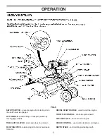
Page 6: ...ing gage wheels TINE CLUTCH LEVER starts and stops tine rotation FLOATING HITCH telescoping hitch limits shock loads to tractor RECOIL START HANDLE used to start the engine THROTTLE CONTROL controls engine speed FUEL SHUT OFF shuts of fuel to engine CHOKE CONTROL used when starting a cold engine DEPTH STAKE controls tilling cultivating depth FIG 5 ...

Page 7: ... ground level and back up tractor to it Slide Floating Hitch of Tiller onto the tractor drawbar so that the hitch pin holes line up Insert hitch pin until it extends through bottom of Floating Hitch Insert hair cotter pin into hitch pin FIG 6 BREAKING IN YOUR TILLER Break in your belts pulleys and the control before you actually begin tilling Start engine with tiller attached to tractor in transpo...

Page 8: ...ROUND TOWN Disconnect spark plug wire Drain fuel tank Transport in upright position to prevent oil leakage TRANSPORTING YOUR TILLER AROUND THE YARD Pull forward on lift handle until it locks in the up transport position AROUND TOWN Disconnect spark plug wire Drain fuel tank Transport in upright position to prevent oil leakage ...

Page 9: ...Change oil every 25 hours when operating the engine under heavy load or in high temperatures Clean more often under dusty conditions or when airborne debris is present Replace air cleaner parts if very dirty Change Engine Oil X X Replace spark plug X Clean cooling system X Check valve clearance X Check for loose fasteners X Lubricate Tiller X Lubricate Tiller Transmission X Service air cleaner pre...

Page 10: ...il as instructed in the separate engine manual Service air cleaner every 25 hours under normal conditions Clean every few hours under extremely dusty conditions Poor engine performance and flooding usually indicates that the air cleaner should be serviced To service the air cleaner refer to the separate engine manual Spark plug replacement is recommended every 100 hours or yearly Check the engine ...

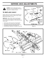
Page 11: ...cracks or frayed edges Refer to figures 11 and 12 IMPORTANT Do not move or remove the belt guide If the position of the belt guide is accidentally altered return it to the correct setting 6 1 2 above the tine shield support plate Remove the screw from the top of the belt guard Remove the hex nut from the rear of the guard Remove the belt guard to allow access to drive belt Disengage tine clutch le...

Page 12: ...ructions in the Service Storage section of the Engine Manual TILLER Clean entire tiller See CLEANING in the Customer Responsibilities section of the manual Inspect and replace belts if necessary See belt replacement instructions in the Service and Adjustments section of this manual Lubricate as instructed in the Customer Responsibilities section of this manual Be sure that all nuts bolts and screw...

Page 13: ...13 TROUBLESHOOTING Follow the instructions in the Service Storage section of the Engine Manual when performing any work on the Engine ...

Page 14: ...1 71 59 45 43 1 3 60 6 4 5 37 2 9 13 74 72 76 75 77 78 7 8 56 55 81 73 62 67 61 23 49 23 63 63 60 60 57 53 23 41 44 22 24 20 30 14 48 42 39 68 82 68 58 69 50 50 27 61 18 23 28 38 11 60 60 40 46 23 11 12 84 47 15 80 80 75 33 64 38 38 19 28 28 28 19 A 38 83 28 28 26 31 21 25 23 14 75 B B C C A 66 28 38 D D 85 86 ...

Page 15: ...ex Lock 39 64284 1 Module 40 43182 4 Hex Bolt 5 16 18 x 3 4 41 HA20112 1 Rear Guard Assembly LH 42 714 0117 1 Pin Hair Cotter 5 32 43 HA20113 1 Rear Guard Assembly RH ref part no qty description 44 HA20094 1 Tine Hub Assembly RH 45 HA20088 1 Tine Hub Assembly LH 46 43054 4 Bolt 3 8 16 x 2 47 47600 1 Bolt Hex 5 16 24 x 1 48 HA5236 1 Pin Hitch 49 43062 1 Bolt 3 8 16 x 1 1 2 Hex Head 50 HA20918 2 Whe...

Page 16: ...15 Bolt Hex 1 4 20 x 5 8 Grade 8 11 HA20125 2 Washer Felt 12 HA20124 2 Seal Rubber 13 HA20130 1 Plug Transmission Oil 14 HA20129 4 Washer Thrust 15 HA20132 1 Chain Assembly 40 16 HA20128 1 Chain Assembly 50 17 HA20133 1 Input Shaft Assembly 18 HA20131 1 Idler Shaft Assembly 19 HA20135 1 Ring Retainer 5 8 Dia Shaft 20 43012 2 Bolt 1 4 20 x 3 4 Hex Head 21 HA20137 4 Bearing 22 HA20145 1 Seal 23 HA20...

Page 17: ...17 NOTES ...

Page 18: ...18 NOTES ...

Page 19: ...19 NOTES ...

Page 20: ...REPAIR PARTS Agri Fab Inc 809 South Hamilton Sullivan IL 61951 217 728 8388 www agri fab com 2001 Agri Fab Inc the fastest way to purchase parts www speedepart com ...

Reviews: