background image

16

67

73

72

70

69

68

66

75

76

74

76

75

74

78

65

50

58

59

60

61

62

64

72

73

52

63

51

54

55

56

57

58

52

77

81

80

79

72

83

85

86

24

23

21

22

21

26

27

28

34

35

36

37

39

47

46

45

49

48

29

No

.01~87  

V1.1   


25

33

12

13

14

03

15

07

06

16

09

05

09

10

17

18

12

19

20

11

01

02

05

04

81

72

83

53

38

30

31

32

41

41

43

42

44

39

48

71

40

84

52

82

82

87


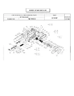
 EXPLODED VIEW 


Summary of Contents for CS320

Page 1: ... over load always run machine with no load for at least 3 minutes to reduce temperature before returning to operation to avoid burn out of the motor ORIGINAL INSTRUCTIONS For your personal safety READ and UNDERSTAND before using SAVE THESE INSTRUCTIONS FOR FUTURE REFERENCE Version 20130909 ...

Page 2: ...ht 8 kg 17 6 lbs Flanges supplied vary with different markets FUNCTIONAL DESCRIPTION Fig 1 Depth Scale Depth Lock Lever Power Supply Cable Main Handle Lock Release Button Load Indicator Light Dust Extractor Port Kicker Lever Side Handle Guide Clearance Adjustor Motor Unit Arbor Lock Lever Base Plate L Hex Key stored in main handle Dust Port Cap Dust Extractor Port Clip Upper Blade Guard Dust Chamb...

Page 3: ... Do not expose power tools to rain or wet conditions Water entering a power tool will increase the risk of electric shock d Do not abuse the cord Never use the cord for carrying pulling or unplugging the power tool Keep cord away from heat oil sharp edges or moving parts Damaged or entangled cords increase the risk of electric shock e When operating a power tool outdoors use an extension cord suit...

Page 4: ...from the power source and or the battery pack from the power tool before making any adjustments changing accessories or storing power tools Such preventive safety measures reduce the risk of starting the power tool accidentally d Store idle power tools out of the reach of children and do not allow persons unfamiliar with the power tool or these instructions to operate the power tool Power tools ar...

Page 5: ...k properly to minimize body exposure blade binding or loss of control 5 Hold tool by insulated gripping surfaces when performing an operation where the cutting tools may contact hidden wiring or its own cord Contact with a live wire will make exposed metal parts of the tool live and shock the operator 6 When ripping always use a rip fence or straight edge guide This improves the accuracy of cut an...

Page 6: ...Investigate and take corrective actions to eliminate the cause of blade binding C When restarting a saw in the workpiece center the saw blade in the kerf and check that teeth are not engaged into the material If saw blade is binding it may walk up or KICKBACK from the workpiece as the saw is restarted D Support large panels to minimize the risk of blade pinching and KICKBACK Large panels tend to s...

Page 7: ...ges as well as the sides of the blade for freedom from any foreign matter 16 Check the blade for cracks or other damage before operation Replace cracked or damaged blade immediately 17 Never start the tool with the workpiece against the blade 18 Allow the motor to achieve full speed before cutting 19 Important After completing the cut release power switch and wait for coasting blade to stop comple...

Page 8: ...nction of the cable length for this machine Use only U L and CSA listed extension cables Never use two extension cables together Instead use one long one 4 Saw Blades Only use saw blades with a diameter in accordance with the markings on the tool name plate Only use saw blades with blade set cutting width of 1 8 mm to 3 6 mm and blade core thickness of minimum 1 5mm to maximum 3 0mm Saw blades mus...

Page 9: ...ghten the blade retaining bolt by turning it clockwise 5 Push in the arbor lock lever and rotate the arbor by hand until the lock engages the arbor Tighten the blade retaining bolt securely Rock the arbor with the wrench to ensure that the arbor lock has released and release the arbor lock see fig 3 REMOVING THE BLADE DISCONNECT TOOL FROM POWER SOURCE Removal is the opposite of installing the blad...

Page 10: ...ARD OPERATIONS To test the function of the lower blade guard rotate the guard through the full stroke of its travel and ensure that the guard is able to fully return back to the closed position under its own spring tension If the guard is found to be sluggish or if it sticks in any position the problem will need to be remedied before the machine is used again It usually just needs to be cleaned To...

Page 11: ...L Make sure that the power circuit voltage is the same as that shown on the specification plate of the machine and that switch is OFF before connecting the tool to the power circuit Switching the machine on and off Keep the machine steady during switching and during use by holding the main handle and the side handles with both hands To switch on first push the lock release button and then press th...

Page 12: ...lways hold the side handle with the left hand and the rear handle with the right hand for proper hand support of the saw Protect your eyes from injury with safety glasses or goggles Do not use cutting fluids or lubricants on the blade Sawing The machine must reach full speed before cutting begins and should only be switched off once cutting has finished Only operate the saw away from you pushing t...

Page 13: ...This can lead to the saw blade jamming and kicking back Instead support the workpiece with several wooden battens close to the cutting face Confirm that the blade has come to a complete stop before removing or securing the workpiece or changing the workpiece angle CAUTION Keep the cord away from cutting area to prevent it from becoming entangled in the workpiece Do not force the cut Let the saw do...

Page 14: ...ly dissolve or otherwise damage the material Wear safety glasses while using compressed air Clean all parts of the lower blade guard mechanism to ensure smooth operation MAINTENANCE The carbon brushes The carbon brushes are a normal wearing part and must be replaced when they reach their wear limit See fig 11 Caution Always replace the brushes as a pair To replace 1 Remove the brush caps and withd...

Page 15: ...15 WIRING 2 1 1 2 AC SWITCH CARBON BRUSH STATOR ELECTRONICS UNIT RED BLACK WHITE LED CARBON BRUSH WHITE ...

Page 16: ...3 52 63 51 54 55 56 57 58 52 77 81 80 79 72 83 85 86 24 23 21 22 21 26 27 28 34 35 36 37 39 47 46 45 49 48 29 No 01 87 V1 1 25 33 12 13 14 03 15 07 06 16 09 05 09 10 17 18 12 19 20 11 01 02 05 04 81 72 83 53 38 30 31 32 41 41 43 42 44 39 48 71 40 84 52 82 82 87 EXPLODED VIEW ...

Page 17: ... M4 x 6 5 40 KICKER MECHANISM 1 41 EXTERNAL CIRCLIP S 10 2 42 PIVOT PIN 1 43 KICKER LEVER 1 44 SCREW M5 x 25 4 NO Parts Name Q TY 45 SCREW M6 x 12 1 46 BUMP STOP 1 47 UPPER BLADE COVER 590g 1 48 PAN HEAD SCREW M4 x 25 5 49 SIDE HANDLE 1 50 GEAR CASE 460g 1 51 SPINDLE 1 52 PARALLEL KEY 5 x 5 x 10 3 53 BALL BEARING 6202 2RS 2 54 INTERNAL CIRCLIP R 35 1 55 SPACER 1 56 OUTPUT GEAR S45CT36 1 57 NUT M14...

Page 18: ......

Page 19: ......

Page 20: ......

Reviews: