
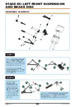
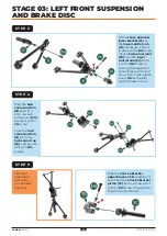


Insert a
hub carrier joint (3K)
into the
upper control arm
(3A) and fix it with a DM screw
by passing it through the hole
marked with a red arrow.
Push the top of the
hub
carrier joint (3K) into the hub
carrier top (3G) and secure it
with a
CM screw.
Position the two
lower control
arm brackets (3J,
marked ‘3’) on the
lower control arm
(3I) and secure each
of them with an
EM
screw, driving each
screw through the
holes marked with a
red arrow.
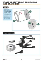
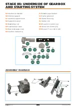
ASSEMBLY DIAGRAM
Secure the
shock absorber lower bracket
(
3F, marked ‘2’) to the shock absorber
cylinder (3E) with a DM screw by passing it
through the hole marked with a red arrow.
S T E P 1
S T E P 2
STAGE 03: LEFT FRONT SUSPENSION
AND BRAKE DISC
13
13
AGORA
MODELS